A good, reliable and easy to use dc power supply is probably the most important thing for every electronics hobbyists. Since a proper electronically stabilized power supply is crucial for almost all microcontroller-related diy projects, here we are presenting a simple diy project of an easy to build and very affordable power supply for microcontrollers.
Circuit Description
The design is centered around TPS63000 (IC1) from Texas Instruments, the high-efficient single inductor buck-boost converter from Texas Instruments (Figure 1). Here the power supply offers a regulated 3.3 V/5.0 V output, processed from an input voltage range of 1.8 V to 5.5 V, with up to 96% efficiency. We can use either a usb port power (through J1), a two-cell or three-cell alkaline, NiCd or NiMH battery, or a Li-ion/Li-polymer battery (through J2) as the input of this power supply.
 |
||
| Figure 1. | Smart Power Supply for Microcontroller Projects. | |
Note that the buck-boost conversion of TPS63000 is based on a fixed frequency, pulse width modulation controller using synchronous rectification to obtain maximum efficiency.
TPS63000 Features:
- Input Voltage Range: 1.8 V to 5.5 V
- Fixed and Adjustable Output Voltage Options from 1.2 V to 5.5 V
- Up to 96% Efficiency
- 1200-mA Output Current at 3.3 V in Step-Down Mode (VIN = 3.6 V to 5.5 V)
- Up to 800-mA Output Current at 3.3 V in Boost Mode (VIN > 2.4 V)
- Automatic Transition Between Step-Down and Boost Mode
- Device Quiescent Current less than 50 μA
- Power-Save Mode for Improved Efficiency at Low Output Power
- Forced Fixed Frequency Operation and Synchronization Possible
- Load Disconnect During Shutdown
- Overtemperature Protection
- Available in a Small 3 mm × 3 mm 10-Pin VSON Package (QFN)
Within the TPS6300x family, there are fixed and adjustable output voltage versions available. Here we used its adjustable ouput version, and connected a resistor divider (R2-R4) between VOUT, FB and GND of TPS63000. If the jumper (JP1) is in open condition, the final output voltage (available at J3) is 5 V, and if the jumper is closed, the same output voltage is locked to 3.3 V.
Circuit Construction
Although implementation of integrated circuits in low-profile and fine-pitch surface-mount packages typically requires high-level skills, the whole circuit can be easily constructed on a piece of small universal SMD prototyping board (ofcourse with the help of a QFN-10 to DIP adapter, Figure 2).
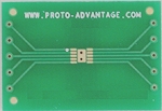 |
||
| Figure 2. | QFN-10 to DIP adapter. | |
According to datasheet, as for all switching power supplies the layout is an important step in the design, the input capacitors (C1 & C2), output capacitors (C3 & C4), and the inductor (L1) should be fitted as close as possible to IC1. Try to use a common ground node for power ground (pin 3) and a different one for control ground (pin 9) to minimize the effects of ground noise (connect these ground nodes at any place close to one of the ground pins of the IC1). The exposed thermal pad of IC1 should be connected to PGND, and the feedback resistor divider (R2-R4) must be placed as close as possible to the control ground pin of IC1. Case option for the device is shown in Figure 3.
 |
||
| Figure 3. | Case option for Smart Power Supply. | |