General information
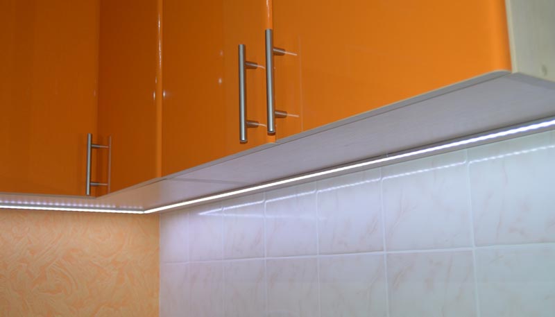
In this article we will talk about a simple device that I designed for automatic control of additional LED lighting in the kitchen. Kitchen renovating and complete replacement of kitchen cabinetry are main reasons for development this device. In my old kitchen work area (desk and sink) lighting was made on LED Strip (5050 LEDs) with a separate switch. There was a sharp shortage of this local lighting after a complete renovation of the kitchen interior (and remove the LED backlight). There were no problems with mounting and placement of LED strip on the new kitchen. But there was no place for inconspicuous installation of the switch. That's why I decided to use the device for automatic lighting control that does not require any action from the user (Figure 1).
 |
|
| Figure 1. | Kitchen working area accent lighting with automatic control. |
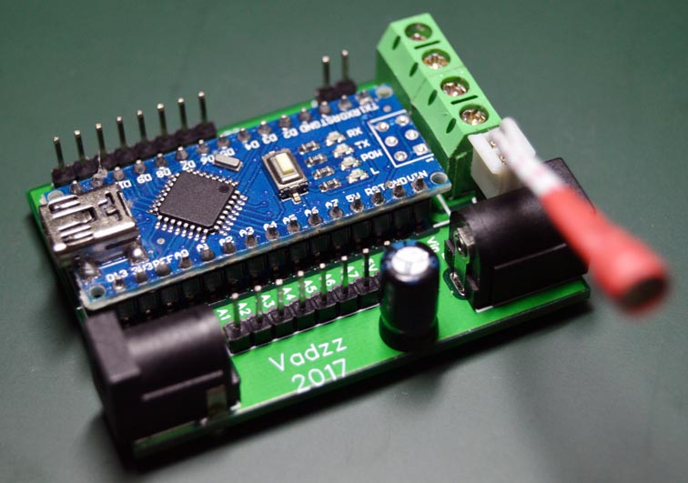
We consider two variants of the device for performing automatic control of the local lighting (work area) in the kitchen. These two controllers differ circuitry and additional functionality. Automatic lighting control means smooth gradual light On/Off switching on the basis of current ambient light in the room (and its sudden change) and the presence of human movement. The first version of the device is made on the Arduino Nano, it operates fully automatically and does not require any action from the user (Figure 2). The second device is made on the NodeMCU (ESP8266 SoC, ESP-12E) Wi-Fi module and, in addition to the basic function it has additional features for online monitoring and control. In the latter case, the user can switch lighting On/Off from browser or mobile application, as well as receive information about the current light level and the controller mode.
 |
|
| Figure 2. | Controllers for automatic lighting control in kitchen working area (Arduino Nano Version). |
The current versions of controller's firmware implements two basic modes of operation: night and day. Basic operations consist of a number of fixed time steps executed sequentially depending on the activity that captures the motion sensor, and a sharp increase in the level of ambient light. For more information about operation modes see "Arduino Sketch Highlights"
In general, both controllers have the same function block diagram: microcontroller, light sensor (LDR), a motion sensor, power supply circuit, the power transistor (MOSFET) for driving LEDs or, as in my case, LED strip. The differences in the circuitry of the controllers because the different specifications of Arduino (AVR microcontroller) and NodeMCU (ESP8266 SoC with Wi-Fi interface), as well as advanced functionality with NodeMCU version. The idea of creating a second version of the controller came after I learned about the cloud service myDevices Cayenne and praised his work on the Arduino platform, and given support ESP8266 chip in Arduino IDE.
Controller Schematic Diagram for Arduino Version
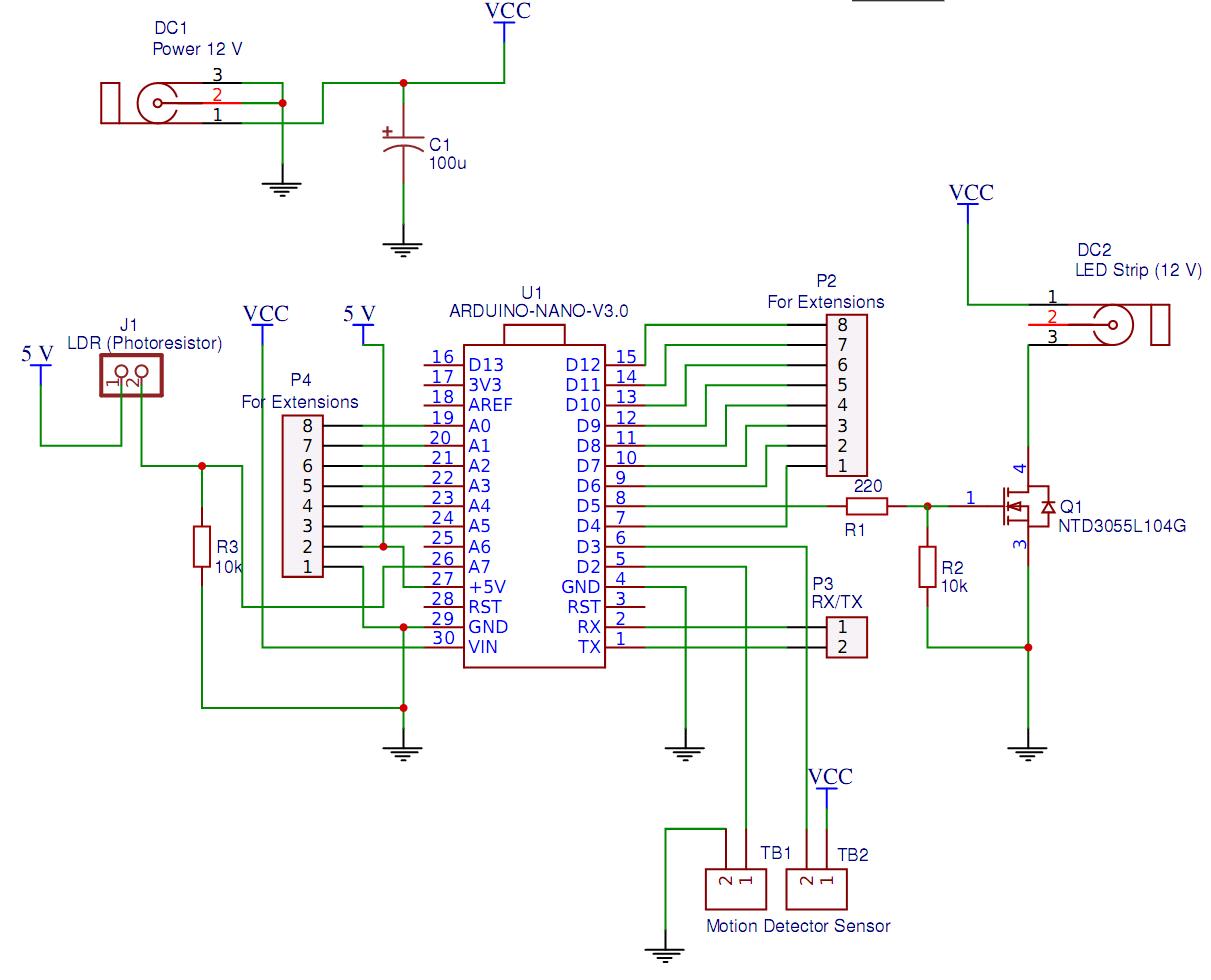
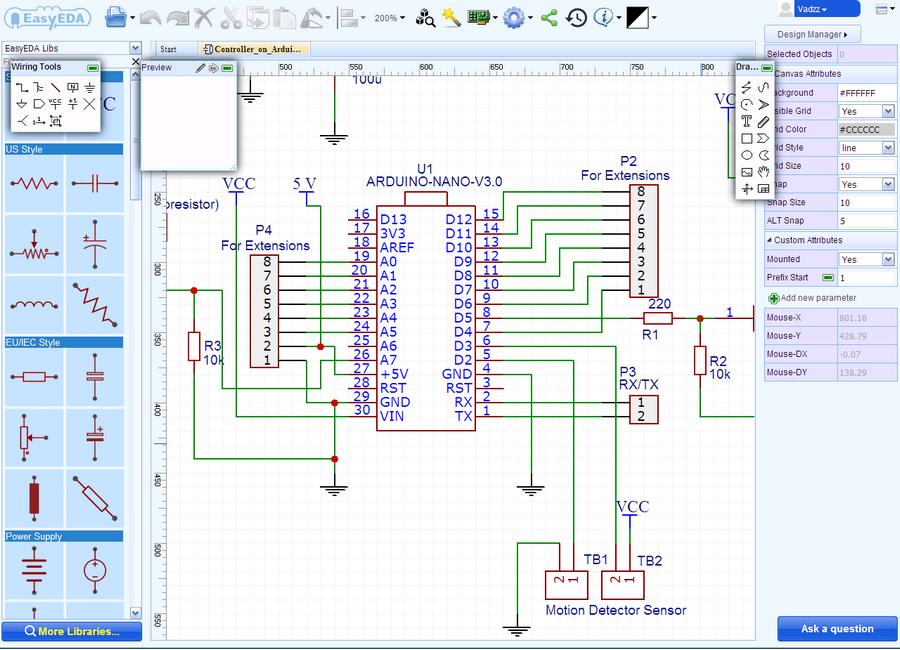
Controller schematic diagram is very simple and is shown in Figure 3. The original circuit (and PCB) is available to users in Web and Cloud-based EDA tool suite EasyEDA, and you can transfer it to your project, for example in order to improve or upgrade, or export to graphic format. Intuitive EasyEDA Interface provides all the necessary tools for the designer, so drawing the circuit has not caused any problems (Figure 4). Note that in the schematic diagram used elements from the primary EasyEDA components database, as well as of the available user libraries.
 |
|
| Figure 3. | Controller for automatic working area lighting. Schematic diagram (Arduino Version). |
 |
|
| Figure 4. | Schematic Diagram development in EasyEDA online editor window. |
As a light sensor I using a miniature LDR VT93N1 (nominal resistance 12 kOhm), in simple wiring diagram (with resistor R3 forms a resistive divider) connected to an Arduino analog input A7.
For human movement detection in a room I used the IR motion sensor Foton-9 from the security alarm system (it is important point, do not confuse with motion sensors to control lighting devices). Any similar motion sensor with normally closed relay contacts and supply voltage of 12 V can be applied without the circuit and firmware changing. Motion sensor connected to the controller by a combined connector TB1-TB2 (screw terminal connectors). The motion sensor signal line (see sensor datasheet) is connected to Arduino port D2, which is configured as an input with internal pull-up resistor. In the normal state motion sensor relay contacts (NC and C) are closed, then to D2 supplied low level. Then motion detected relay opens and the internal pull-up resistor provides high level on D2 input.
Note that the IR motion sensors from different manufacturers have different sensitivity (in most cases, regulated) and detection pattern, so the choice of sensor mounting location is time-consuming process. In my case, the sensor is located in the upper right corner opposite the kitchen entrance (Figure 5) and, thanks to the good sensitivity, is triggered by a person approaching the entrance to the room, so the light turns on in advance.
 |
|
| Figure 5. | Location of controller with LDR, IR motion sensor and main lighting. |
Pin 2 of terminal connector TB2 is connected to a free Arduino port D3 and can be used to extend the functionality of the controller. P2-P4 connectors can also be used to extend functionality.
Light-emitting diodes, or LED strip with supply voltage 12 V connected to the DC2 connector. The microcontroller implements PWM mode for LED brightness control using power MOSFET NTD3055L (or similar with logic level control), whose gate is connected to the Arduino digital output D5 (PWM).
Arduino Nano board includes 5 V voltage regulator for the microcontroller power supply, so no need to use additional voltage regulator, and the 12 V (from external power supply) with the DC1 terminal is supplied directly to the Arduino Vin pin. From Arduino board 5 V used for LDR and the P4 connector (Pin 2).
Arduino Sketch highlights
The microcontroller source code (sketch) is easy to understand and provided with comments. Sketch is provided "as is", I do not exclude the possibility of further optimization or implementation of additional functions, and the controller operating modes. It all depends on your imagination and desires.
Current light level data and its changing microcontroller receives from LDR. Integrated analog-to-digital converter converts the voltage value on A7 analog input in digital code which is used unmodified in the program without any conversion. This digital code for simplicity the following description can be defined as some conditional units.
As I noted at the beginning of the article, the controller implements works in night and day mode. These are the main modes of operation, which are carried out in stages:
- Day mode is active in a room with lack of light (15 - 110 conditional units):
- Step 1:
When motion is detected, the light glows smoothly at a brightness of 20% for 3 minutes. Go to step 2 if the movement is fixed at the end of this step. Gradually turn off the backlight, if there is no motion. - Step 2:
Start counting interval 7 minutes after smooth increase in brightness up to 100%. The time counter is reset to 0 every time the motion is fixed; - Step 3:
Go to step 1 after the interval of 7 minutes (no movement). The brightness gradually decreases to 20%.
- Step 1:
- Night mode is active in low light (less than 15 conditional units):
- Step 1:
The light glows smoothly with a brightness of 10% for 3 minutes when motion is detected. Go to step 2 if the movement is fixed at the end of this stage. Gently turn off the backlight, if there is no movement; - Step 2:
The brightness gradually increases to 50%. Start the countdown interval of 7 minutes. The count starts from 0 with each motion fixation; - Stage 3:
The brightness gradually decreases to 0 after an interval of 7 minutes.
- Step 1:
I explained the description and the selection of the appropriate operating modes in the sketch (source code) with comments.
A sharp change in light level (main light turn On) controller determines from the difference between two consecutive measurements of illumination. Measuring the light level is performed every second. The LightingChange_Det() function is used for this purpose. The controller, according to the current basic mode of operation, will move to the next stage if a sharp increase in illumination is detected (a difference of more than 40 in the ADC code). In this case, the backlight will turn on or increase its brightness (Listing 1).
Listing 1. The ambient light level measurement function.
void LightingChange_Det () {
  current_luminosity = analogRead(Light_Sensor);
  if ((current_luminosity - previus_luminosity > 40) && (Light_On == false)) {
    mode = 1;    //If main light On and working area light is Off;
    Mode_Set();  //Then working area light turn On (day mode, step 1)
  }
  if ((current_luminosity - previus_luminosity > 40) && (Light_On == true) && (mode == 1)) {
    mode = 2;    //If main light On and working area light is On (day mode);
    Mode_Set();  //Then increases brightness (day mode, step 2)
  }
  else if ((current_luminosity - previus_luminosity > 40) && (Light_On == true) && (mode == 4)) {
    mode = 5;    //If main light On and working area light is On (night mode);
    Mode_Set();  //Then increases brightness (night mode, step 2)
  }
  previus_luminosity = current_luminosity;
  if ((current_luminosity > 110) && (Light_On == true)) {
    mode = 0;    //sufficient ambient lighting in the room
    Mode_Set();  //working area lighting Turn Off
  }
}
The level of lighting in the room is also controlled in this function. The backlight does not turn on or the brightness level decreases smoothly to 0, if it has become sufficient (more than 110 units). It should be noted that, the controller is located on overhead kitchen cupboards and basic lighting is performed by dot LED lights in my case. Therefore, the LDR is not exposed to light from main lights or natural light from the window, nor from LED strip for working area. Note that the photoresistor reacts more strongly to natural light than to artificial light (LED lamps) in this arrangement.
All time delays in the sketch are generated without function delay(). Construction based on function millis() is used.
Listing 2. Implementation of timeslots using millis() function.
if (millis() - timeout_1 >= interval_1) {     //1 s interval
    timeout_1 = millis();                     //Light Level measuring every second
    LightingChange_Det();
  }
Checking all conditions and selection of the required mode is performed with the help of the operators «if ... else». Direct control of PWM output in accordance with the established operation mode is performed in a separate function Mode_Set(), which uses «switch ... case» operator.
Set up the operating modes of the controller is not difficult. It will be necessary to determine the levels of illumination for night and day operation, the operating time of the steps, and also to determine the change in the illumination level when the main lighting is switched on. To simplify the configuration, you can include debug information output functions in the source code.
Source Code (sketch) is available for download in the download section.
Printed circuit board (PCB)
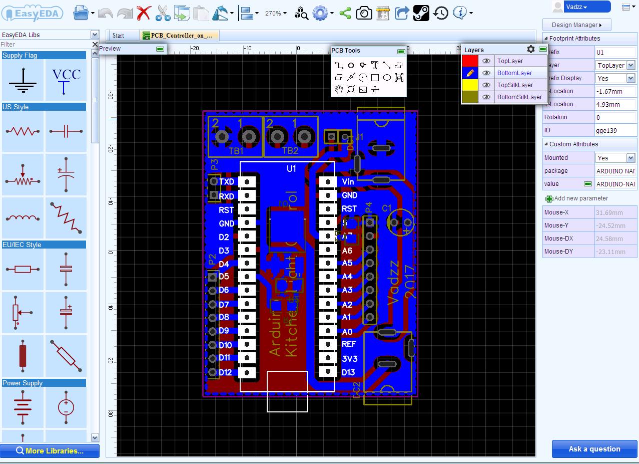
The Printed Circuit Board of the controller is also developed in online EasyEDA PCB editor from schematic. Placing packages of the elements specified in the schematic, and their grouping within the board edge can be carried out automatically at one click in the editor. Components packages are placed consecutively and compact, but do not overlap each other. As well as the schematic diagram creation in EasyEDA, the PCB design are very easy and quick (Figure 6).
 |
|
| Figure 6. | PCB Designing in EasyEDA. |
After manual placement of components on the board you can perform an automatic trace or draw traces in manual mode. The autorouter is very easy to set up, works quickly and efficiently. All the tools needed for manual drawing and editing elements, layers, switching display modes are available in the control panel.
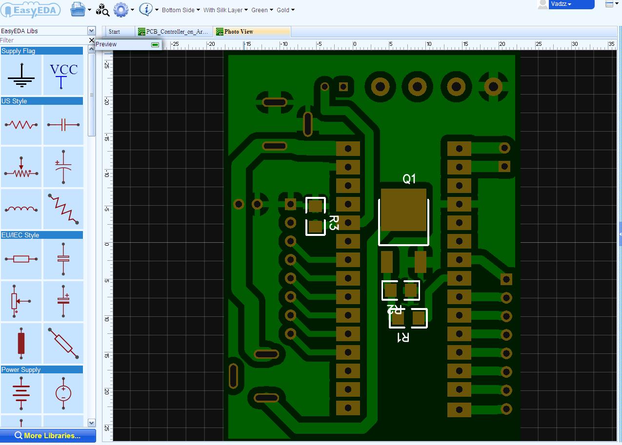
PCB for controller is double-sided, but without vias. For top and bottom layer I use “Copper Area” with GND and silk-screen printing on the upper layer (Figure 7). PCB production order issued directly from the editor, it will automatically be generated Gerber-files of my project (file is available for download in the downloads section). In addition, EasyEDA built a very useful tool for viewing Gerber-files - GerberViewer. Minimum order (5 pcs.) was carried out within 3 business days and mailed.
 |
|
| Figure 7. | Photo view of the printed circuit board in EasyEDA editor. |
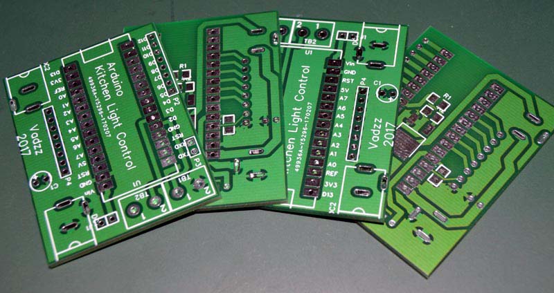
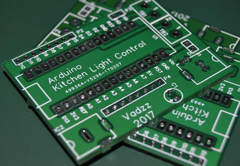
Boards quality is very pleased (Figure 8). Perhaps this is not the case to judge the equipment and production capabilities, due to fairly wide printed conductors and large gaps, but looks good. The quality of the tracks, silk-screen, plating holes have no complaints. All sizes, including diameters of the holes correspond to the project, the findings of all the elements installed in the holes without effort.
 |
|
 |
|
| Figure 8. | The set of printed circuit boards manufactured in EasyEDA. |
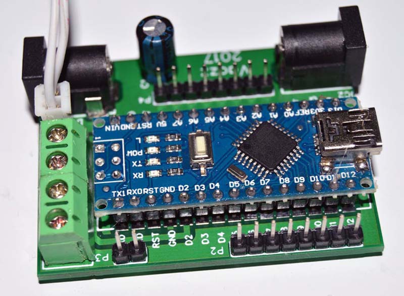
Board with mounted components is shown in Figure 9.
 |
|
| Figure 9. | Controller PCB with mounted components. |
| Table 1. | BOM | ||||||||||||||||||||||||||||||||||||||||||||||||||
|
|||||||||||||||||||||||||||||||||||||||||||||||||||