When you need an analog output from a microcontroller that does not have a digital-to-analog converter (DAC), you can connect an external DAC chip. But for a cheaper solution, use a pulse-width modulated (PWM) output and add a low-pass filter (LPF) to extract its average value, which equals the duty cycle of the PWM signal (Figure 1).
 |
||
| Figure 1. | An RC LPF extracts the average value of a PWM signal | |
The RC filter removes the non-DC components; what remains is the average signal UOUT. If the period T of the PWM signal equals 63 clocks, the signal UOUT can have one of 64 discrete DC values (0 to 63, six-bit resolution).
 |
||
| Figure 2. | The filtered output (blue) should have less than one LSB of ripple. | |
The time constant t of the low-pass RC filter must be big enough to smooth the output signal UOUT. The ripple, ∆UOUT, should be less than one least significant bit (LSB). The worst case occurs with a duty cycle of 50% (Figure 2). If t is much bigger than the period T then the capacitor charging current IC and the change ∆UOUT can be approximated as:

and from

it follows

For a 6-bit DAC, ∆UOUT should be less than VCC/64, requiring a filter of t = RC ≥ 16×T.
Some practical numbers: low-power microprocessors often use a crystal oscillator of 32768 Hz, and this clock signal is used for the PWM block. With 6-bit PWM, the period T is 64/32768 ≈ 2 ms, necessitating a time constant of 32 ms. One has to wait 5t (160 ms) for a 6-bit converter to settle. Slow. This Design Idea explains how you can speed things up.
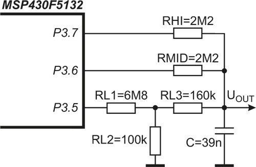
PWM blocks in microcontrollers can usually generate more than one PWM signal. Consider summing outputs from two PWM based 3-bit DACs (DACH and DACL), where the output of DACL is reduced to one-eighth amplitude before adding. The resulting signal acts as a 6-bit DAC, with an important advantage over the simple version: the period T is only eight clock periods for the same resolution, and the required time constant t is 1/8 of the previous, speeding up settling time by factor of eight. Such an arrangement is easy to implement with resistors in the RC filter for two PWM signals (PWMH, PWML) (Figure 3).
 |
||
| Figure 3. | Combining two PWM-based DAC outputs. | |
The output signal UOUT is given by:

This technique has been implemented in a TI MSP430F5132 microcontroller (Listing 1):
Listing 1. Code to initialize & write to a 6-bit (3+3) PWM-based DAC.
// configure PWM - 32 kHz / 8 = 4 kHz :: 6 bit in two PWMs, done only once on power-up
TA0CCR0 = 7; // count up to 7 (including)
TA0CTL = TASSEL__ACLK | MC_1 | TACLR;
TA0CCR1 = 0; TA0CCTL1 = OUTMOD_6; // toggle/set
TA0CCR2 = 0; TA0CCTL2 = OUTMOD_6; // toggle/set
// use :: write to PWM block to achieve the desired DAC output
DAClevel++; // next DAC level, DAClevel is a char
TA0CCR1 = (DAClevel >> 3) & 7; // set PWMH: MSB 3 bits
TA0CCR2 = (DAClevel ) & 7; // set PWML: LSB 3 bits
 |
||
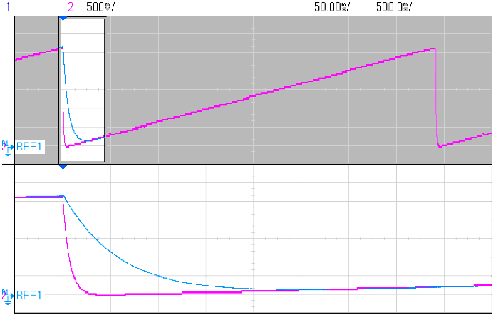
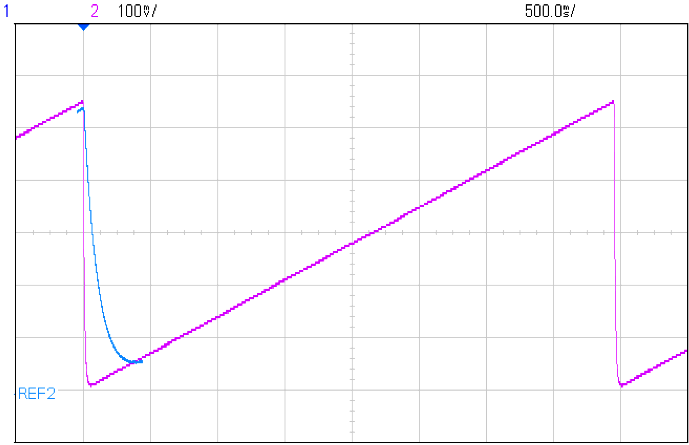
| Figure 4. | Measured outputs from 6-bit PWM-based DACs; Blue: implementation as in Figure 1 (160 ms settling); Violet: implementation as in Figure 3 (20 ms settling). |
|
A 7-bit DAC (Figure 5) can be implemented using 1% resistors. This time, two PWM signals are used to make two three-bit DACs, totaling six bits, and the MSB is simply set to 0 or 1 at P3.7 (Listing 2).
 |
||
| Figure 5. | An implementation of a seven-bit PWM-based DAC. | |
Listing 2. Code to initialize & write to a 7-bit (3+3+1) PWM-based DAC.
// configure PWM - 32 kHz / 8 = 4 kHz :: 7 bit in two PWMs and one digital pin, done only once on power-up
// is the same as given in configure section in Listing 1
// use :: write to Timer comparators to achieve the desired DAC output
DAClevel++; // next DAC level, DAClevel is a char
TA0CCR1 = (DAClevel >> 3) & 7; // set PWMH, MSB, 3 bits
TA0CCR2 = (DAClevel ) & 7; // set PWML, LSB, 3 bits
if (DAClevel & BIT6) P3OUT |= BIT7; else P3OUT &= ~BIT7; // set MSB, no PWM
 |
||
| Figure 6. | Measured output of Figure 5 circuit; note the good linearity. | |
The speed improvement here is even greater. A simple PWM DAC would have a period of 128 clock periods (128/32768 s-1 = 3.9 ms), resulting in t of 32·T = 125 ms and a settling time of 5×125 ms = 625 ms. Figure 6 settles in 40 ms — 16× faster. A higher-order LPF would also help to reduce settling time.
References:
- Stephen Woodward: Fast-settling synchronous-PWM-DAC filter has almost no ripple
- David M. Alter: Using PWM Output as a Digital-to-Analog Converter on a TMS320F280x Digital Signal Controller
- Mike Mitchell: Using PWM Timer_B as a DAC
- Amar Palacherla: AN538: Using PWM to Generate Analog Output