Although you can obtain universal, resistor-programmable switched-capacitor filters that are configurable as notch filters, most cannot operate at bandwidths higher than 100 kHz. Further, the typically 16- to 20-pin packages do not include a continuous-time, antialiasing filter to prevent spurious signals from appearing at the output. By using an eight-pin, dual operational amplifier and an eight-pin, switched-capacitor bandpass filter, you can construct a notch filter (Figure 1). IC2, a TLC082 is a dual BiCMOS op amp, replacing the older JFET-input stage with lower noise CMOS but retaining the bipolar output for high drive capability. The gain-bandwidth product of the TLC082 is 10 MHz, allowing you to use it for filtering at frequencies as high as 1 MHz. The minimum (VCC–VEE) span with the TLC082 is 5 V, unlike the older TL082, which required 6 V. This supply span matches well with IC1, an MSHFS6, with its 5 V nominal operating voltage. Using half of the TLC082, you can construct a third-order, elliptic lowpass filter.
 |
||
| Figure 1. | An op amp and a switched-capacitor filter combine to form a highly selective notch filter. |
|
 |
||
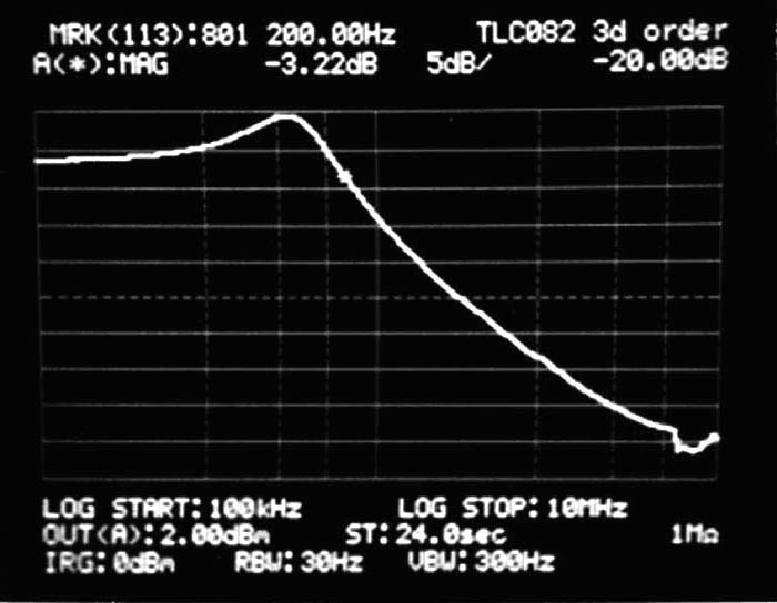
| Figure 2. | This plot is the frequency response of the third-order lowpass-filter stage. |
|
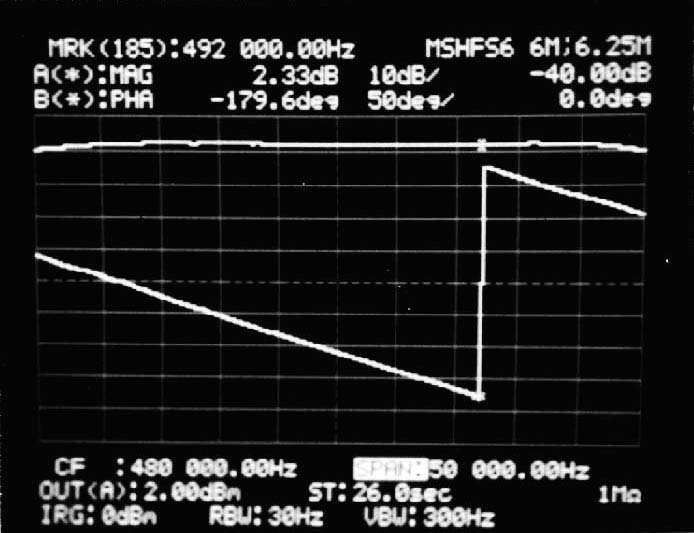
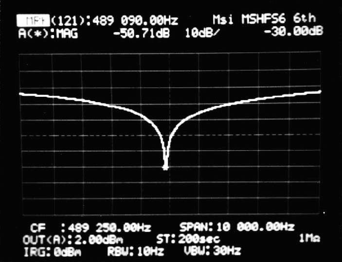
You set the passband ripple at approximately 5 dB to increase the out-of-band rejection. You set the continuous-time filter for 800 kHz, providing greater than 40 dB of rejection at 12.5 MHz. Figure 2 shows the frequency response of the third-order lowpass filter using the TLC082. The MSHFS6 switched-capacitor selectable lowpass/bandpass filter with its 12.5-to-1 clock-to-corner ratio allows for distortion measurements to 6.25 times the notch center frequency before aliased signals cause measurement error. With the TLC082 lowpass filter set at 800 kHz, you can measure distortion products as high as the third harmonic. If the notch center frequency is always set lower than 260 kHz (MSFS6 clock at 3.3 MHz), then you can set the continuous-time lowpass filter corner to a lower frequency by adjusting the resistor and capacitor values. By summing the output of the bandpass filter with the input, cancellation of the input signal occurs at 180° phase shift in the passband. Figure 3 shows the Bode plot of the passband of the MSHFS6 sixth-octave filter setting. The output of the other half of the TLC082 provides the notch-filter output. Figure 4 shows the depth of the notch filter at –50 dB.
 |
||
| Figure 3. | This Bode plot represents the passband of the MSHFS6 filter. |
|
 |
||
| Figure 4. | The circuit in Figure 1 delivers a –50-dB notch. | |