After seeing so many applications using acceleromters making a simple project of my own with this cool sensor just seemed natural.
The main application of the accelerometer is either for sensing tilt or sensing acceleration. For this application A G-Force meter for my car will be made to see how many "G's" I pull while driving.
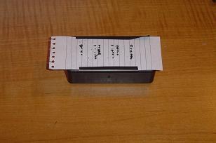
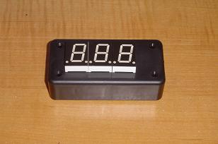
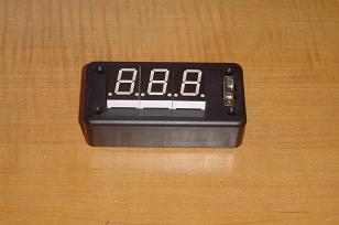
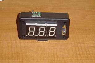
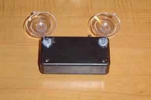
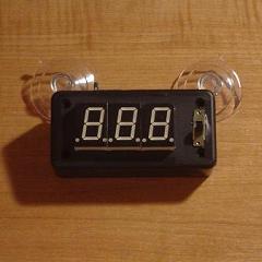
Below is an example of what the Personal G-Force Meter offers you and how it fits nicely right onto your dash. I put suction cups on it as well but they weren't necessary.
The Personal G-Force Meter

Purpose & Overview of this project
The purpose of this project is to build a device that measures acceleration/tilt on one axis (backward/fordward) capable of fitting onto the dashboard or hanging onto the window of a standard car.
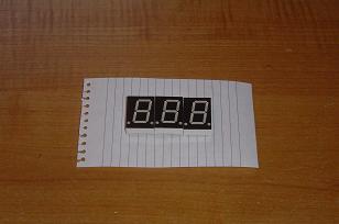
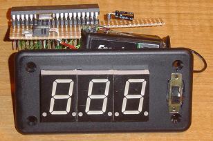
The device will have 3 7-Segment LED Displays to show the instantaneous acceleration measurement to 2 decimal accuracy.
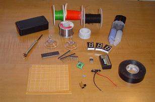
Parts List Details
You may or may not be familiar with the parts above so a picture of each item has been included to help give you an idea of what they look like. I'll go through and explain the key parts below.
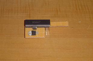
PIC 18F452
The PIC will be the brains of this project. The A/D's on it will be used to take the data, then it will interpret that data and finally output it in a way we can understand on the 7-Segment LEDs. This whole process will be taken care of in the software.
ADXL320 Accelerometer
This is the main sensor for this project. It detects accelerations or tilt and then outputs an analog value equivalent to the change. The datasheet for this device is very straight forward and should answer any lasting questions you might have about the sensor.
7-Segment LEDs
The 7-Segment LED Displays will be used to output the measured g-force in the X.XX form where the X's will be numbers. The PIC will directly control the output shown on these dispalys.
20 MHz Crystal
The speed of the processor will be set to 20 MHz for no other reason than that is the first crystal oscillator that I found when I was looking for parts. A 4 or 8 MHz oscillator could be used instead.
Schematic Overview
The Schematic has three main parts to it. The Sensor Circuitry where the accelerometer is wired up to the A/D converters. The second part is the power circuit where we have the On/Off switch, the 9 v battery & +5 v 7805 Voltage Regualtor. The 3rd part of the circuit is the 3 7-Segment LEDs.
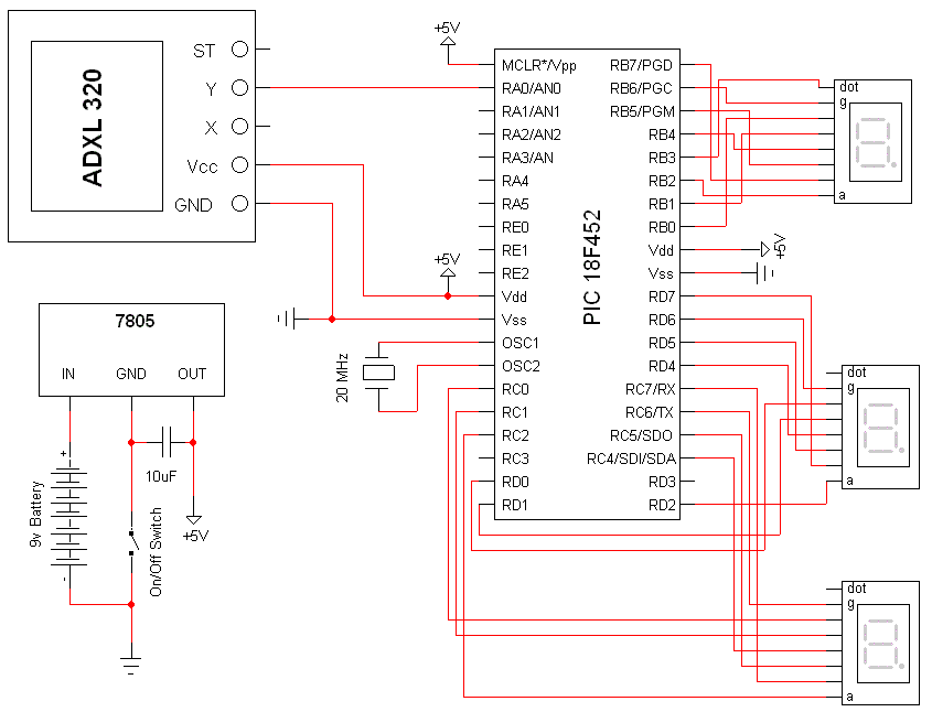
Schematic Specifics
- Power Circuit The power circuit is a 9 v Battery hooked up to the LM7805 with a 10 uF capacitor wired to output & ground of the LM7805 to keep a steady 5 v DC.
- Sensor Circuit The sensor is very simply wired with one wire from the Y-axis measurement spot to the AN0 port on the PIC. This is an analog input port and we'll use it as such. The other pins on the sensor aren't used, aside from Vcc & Gnd.
- 7-Segment LEDs The wiring of the 3 7-Segment LED displays may seem somewhat random. The reason it looks strange is because I wrote the software and wired everything up before drawing out a proper schematic. This made my schematic drawing look pretty strange but the software and the actualy wiring very straight forward.
The Theory
The theory for this project is heavily based upon the topics covered in the accelerometer tutorial. The theory is that the sensor measures accelerations with respect to the earth's own gravity which means it can also be used as a tilt sensor. The following video demonstrates how the sensor can also be used to measure 'tilt':
How The Accelerometer Works
Many different accelerometers are available and there are many different types of methods used to measure acceleration using them. A popular method is to use a bubble inside the chip and then to measure that bubble's movement based on certain variables.
Hardware Design
Now that we've seen the schematic and a little bit of the theory let's take a look at the step-by-step process for building your personal g-force meter.
Step (1) - Gather All The Parts Previously Mentioned»
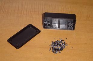
Step (2) - Clear Out The Insides Of The Plastic Enclosure»
Step (3) - Map The Pinout Of The 7-Seg LEDs On a Piece Of Paper»
Step (4) - Drill Tiny Holes For Each Pin Of The 7-Seg LEDs»
Step (5) - E-poxy the LEDs Onto The Enclosure»
Step (6) - Drill A Hole For The On/Off Switch & E-poxy It In»
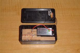
Step (7) - Cut Your Proto Board To Fit Into The Enclosure»
Step (8) - Notice The L Shaped Protoboard Leaves Room For A 9 v»
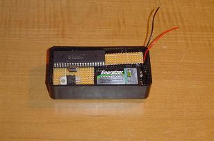
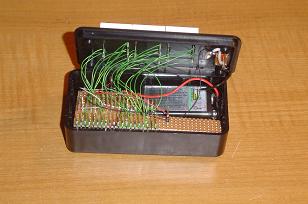
Step (9) - This Is How Things Should Go Inside The Enclosure»
Step (10) - Wire-up The Board According To The Schematic»
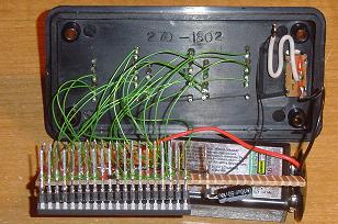
Step (11) - Front-View Of The Finished Wiring»
Step (12) - Drill Holes For The Accelerometer»
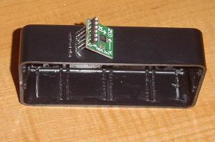
Step (13) - E-poxy The Accelerometer Onto The Enclosure»
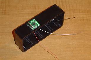
Step (14) - Wirewrap The Accelerometer To The PIC»
Step (15) - Tape The Surrounding Edges With Electrical Tape»
Step (16) - E-poxy The Two Suction Cups Onto The Back»
The Software
The software for this project is limited to only a few parts. The A/D capture, conversion to a non-decimal numerical representation of the g-force and then that value is passed to a function that takes care of the output.
Since most of the code is pretty straight forward in terms of output data, I'll just focus on the main algorithm that gets the data from the sensor and make sense of it. The main algorithm that I used was adopted from this project by the guys at Dimension Engineering. I updated it and changed it for the C18 compiler as well as changed a few parameters to better match the sensor.
----- Begin Code -----
while(1){
update_char_display(char_disp); //Update 7-Segs
Delay1KTCYx(250); //Delay A Little While
Delay10TCYx(5); //Redundant Delay For A/D
ConvertADC(); //Do A/D Conversion
while( BusyADC() );
current_result = ReadADC();
temp = current_result - past_result;
//If Only A Slight Change Don't Update
if( temp > 2 || temp < -2 )
{
past_result = current_result;
g_val = current_result - gravity_ss;
g_val = g_val << 5;
g_val = g_val / display_divider;
if(g_val < 0)
g_val = g_val * -1;
i = 2;
}
while(i!= 255)
{
char_disp[i]=g_val%10;
g_val = g_val/10;
i--;
}
}
----- End Code -----
The algorithm above won't make much sense unless you're familiar with how the accelerometer work. First it looks at the change in A/D results, if that change is large enough to warrant the display to get updated it proceeds. The result is subtracted from the gravity steady state value which will be 512 @ 0 G's. What we do next is shift the values to the left and use a known display divider (in this case it is 20) to get the same value that we had before but in non-decimal form. So changing 1.23 => 123. This will make updating the display significantly easier.
Data & Observations
The Personal G-Force Meter is tested out with me driving around. My car is pretty weak so it doesn't pull many g's when accelerating. It can however do pretty good at negative g's while breaking, however I wasn't able to get over 0.8 G's. Watch the video:
Initial thoughts about the sensor are that it could really use a filter so that the data output would be more accurate and not so unstable. Many different types of software filters could be applied but I chose not to use them for the sake of seeing the raw data output. I leave it up to you guys to improve upon the 'base' design.
An Overview Of The Personal G-Force Meter
The entire system is a straight forward sensor to microprocessor to output design. There is little practical use for such a device other then novelty. The sensor could of course be used for a true application as accelerometers already are. However, this project was done like all other, for the sake of fun.
What To Do Now
There are many directions that you can take with the information learned in this project. The first thing to do would be to experiment with FIR or IIR filters to get better data from the sensor. Other places to go to would be to try and track inertial movement with the sensor.
Conclusion
This project was one of the funner projects because now I have a new gizmo for my car. It was definitely a success as the measurements are what they should be and the meter also acts as a tilt sensor. Hopefully you learned something through reading this project write up!
If you have any further questions, I implore you...don't be shy, take a look at the forums or ask a question there. I check them out regularly and love getting comments & questions.