This is a simple project of a sundial wherein the pinion is replaced by a line LASER I took from a LASER level. The LASER is mounted on a RC servo which in turn is driven by a micro controller. The micro controller keeps the time and turns the RC servo accordingly.
Very basic in design it does exactly what I wanted and has as few parts as I could.
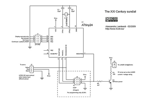
The micro controller is an Atmel Attiny24 with crystal for better accuracy. The internal RC oscillator could be calibrated but in the end the precision can be achieved from a crystal quartz only.
The schematic is very simple, just the micro with crystal and capacitors, the LASER and the transistor necessary to drive it, the servo. The power supply comes from a 5Volt wall adapter.
The micro controller runs a real time clock. Time is converted into minutes from 1:00 hours and converted in PWM pulse which is suitable to drive an RC servo. The source code is well commented, I’d say, and can be easily followed to understand how it works. In case, just comment and ask.
J4 is necessary to program the micro with the In Circuit Serial Programming faciliy like the one provided by the AVR Dragon debugger. If you have the micro already programmed (by a friend, say) you don’t need to mount that. Just be careful not to leave unconnected the R2, J2 and Pin 7 node also…
Upon power on the servo swings from about mid position of the sundial to 1:00 hours. Short pins 5-6 of J1 to make the sundial advance 1 hour at a time. Let it go a few times from 1:00 to 12:00 to see the rotation span. Then remove the short when the LASER points to the right hour.
To set the minutes it might be easier to set the time at the exact hours as the minutes are set to 0 whenever hours are set. Otherwise just short pins 3-4 of J1 counting 2 every second and remove the short when at the correct minute.
Shorting pins 1-2 adds some life to the sundial and makes it count just the seconds. Hypnotic initially, then pointless.
Shorting pins 7-8 makes the LASER on continuously, otherwise it blinks every second, like in the video below.
The circuit and software can be modified to display different things like a voltage at an analog input of the micro making a LASER analog meter. Or to make something like a LASER chronulator.
More of these circuits can be superimposed to display different values on the dial.
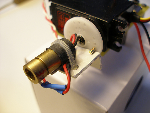
This is a picture of the thing.
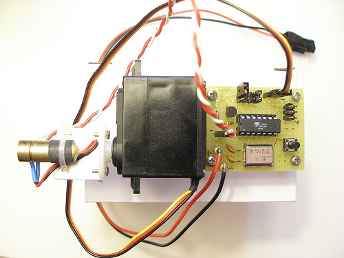
The servo I used is a Hitec HS-300BB, a pretty good one I happened to have in a drawer. Any other servo would do, the rotation span being probably a little bit different. It can be adjusted with the SERVO_MIN and SERVO_MAX defines but recompiling would be necessary.
I did not use a PCB, I actually built an UV bed to make PCBs but I never get to the point of actually making one…in case : http://www.instructables.com/id/The-return-of-the-dead-flatbed-scanner/
The pictures show how I attached the LASER to the RC servo : an L-shaped piece of Aluminum, a few tiny screws and a teflon fastener did the job easily. The tricky part is to make the lower end of the LASER line aligned with the center of the rotation of the servo. Anyways, misalignment might give some interesting visual effects when the LASER line does not rotate along one of its end but around a point somewhere in between like the hand of a speedometer. Just experiment.
The software.
It is written in C and compiled and debugged in AVR Studio. I debugged the code with the AVR Dragon which uses the In-circuit debugging capabilities of the ATTiny24.
The code is commented and should be readable and modifiable as desired in any case a few comments follow.
#define F_CPU 2457600UL // crystal frequency
#define PWM_TOP F_CPU/60 // == 40960 is TOP count for timer 0 (goes into OCR0A)
These pre-compiler instructions define the frequency of the crystal and the value to the placed in the OCR1A register which is going to be the maximum count for timer1 before resetting to zero. We want the PWM frequency to be 60Hz. We are using these 60Hz pulses as the time base for the real time clock also.
The following lines set up Timer1 with fast PWM, no prescaler (that is, the crystal frequency goes straight into Timer1), and PWM compare output is on OC1B pin (read on)
TCCR1A = _BV(WGM11) | _BV(WGM10) | _BV(COM1B1);
TCCR1B = _BV(WGM13) | _BV(WGM12) | _BV(CS10);
OCR1A = PWM_TOP; // PWM freq = 60Hz
Timer1 now runs from 0 to PWM_TOP which happens 60 times every second (2457600/40960)
The instructions above also make the output pin OC1B high when the counter is below OCR1A and zero otherwise (PWM compare). This is PWM : changing the value in OCR1B from 0 to PWM_TOP makes the duty cycle output from 0% to 100% at the PWM frequency which do not change : 60 pulses every second, the pulses are simply thinner or larger.
The exact meaning will more clear when checked with the datasheet of the ATTiny24.
The following instruction places the servo at OCR1B output halfway between the maximum and minimum position of the servo.
OCR1B = (SERVO_MAX + SERVO_MIN) / 2;
This is not 50% PWM duty cycle, as the servo does rotate from min to max with pulses smaller than 50%, that’s why I defined SERVO_MAX and SERVO_MIN based on the the length of the pulses that place the servo at maximum or minimum:
#define SERVO_MAX PWM_TOP*1.65/(1000/60) // max rotation is at 2.35ms pulse
#define SERVO_MIN PWM_TOP*0.75/(1000/60) // min rotation is at 0.70ms pulse
Now I want the timer overflow to be used also as the timebase for the real time clock :
TIMSK1 = _BV(TOIE1); // enable timer overflow (for real time clock)
sei(); // enable global interrupts
Now every 1/60th of a second the following routine is called :
ISR(TIM1_OVF_vect) { … }
This routine does a number of things :
It counts the real time, 60 times1/60th of a second makes one full second elapsed, so the counter of seconds is incremented together with minutes and hours if required.
It also blinks the LASER for 1/10th of a second every second unless the relevant pin short strips shorted,in which case the LASER is always on.
This routine evaluates also the position to be given to the servo to make it rotate as needed. To do so the time is converted into total minutes elapsed from time 1:00 and the result scaled into the range SERVO_MIN to SERVO_MAX.
servo_pos = servo_min + ((hour-1)*60+min)*((servo_max-servo_min)/(11*60+59));
Shorting JUMP_0 makes the servo display the seconds only (9 to 59) thus the calculation as of above is made on current seconds only and minutes/hours disregarded :
servo_pos = servo_min + sec*((servo_max-servo_min)/59);
The following places the servo in the mirror position to make the LASER rotate clockwise :
OCR1B = servo_min+servo_max-servo_pos; // clockwise
// OCR1B = servo_pos; // counter clockwise (commented out)
If needed the first line can be commented out and the double ‘//’ removed from the second line : this would make (after compiling and downloading to the micro) the servo run counter clockwise.
Finally the routine also checks pin short strips for time set and sets hours and minutes if required. Minutes advance 1 every half a second while hours once per second. Removing the shorts resume regular clock display.
If you are going to modify the and recompile with AVR Studio with AVRGCC, the C compiler, don’t forget to set the fuses to External Crystal mode 0.9 to 3MHz, no watchdog, x8 clock divider disabled. All other fuses should be default.
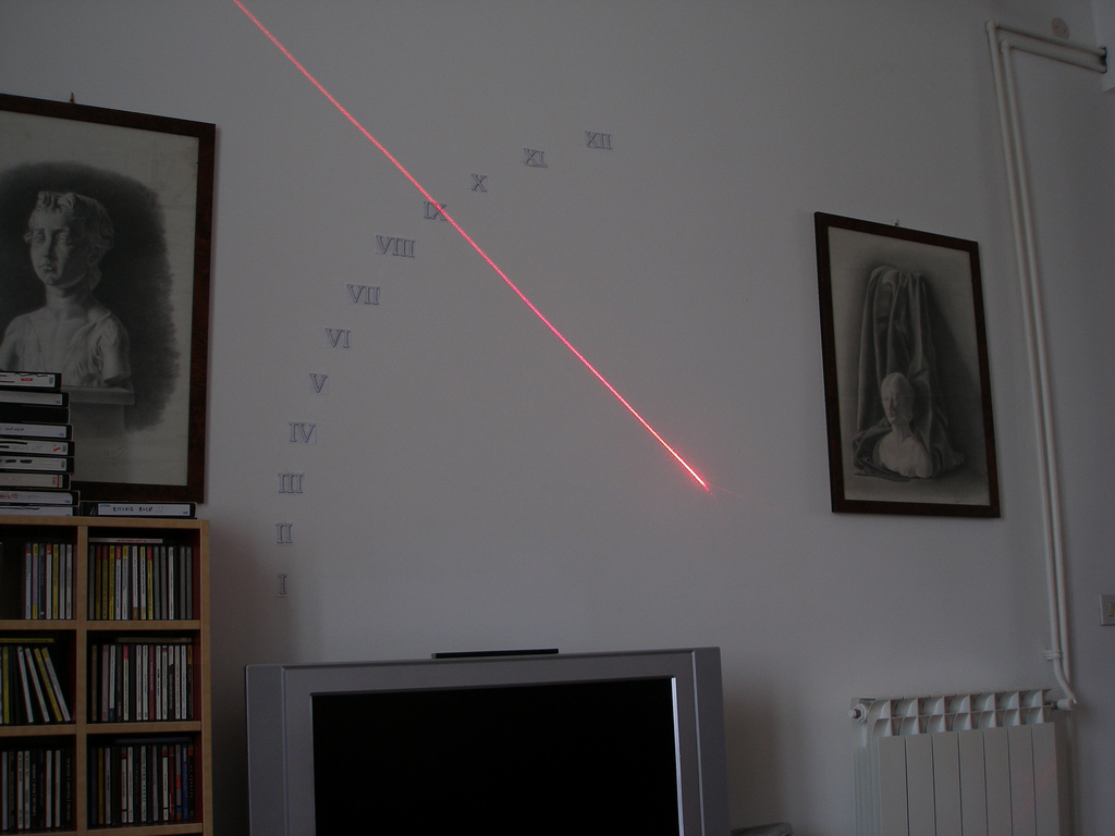
You can see a video of the sundial below. Please trust me when I say that the light pulses much better than in the video : the bad flicker or disappearing light is just caused by low frame rate, poor camera ( and poor operator ? ). I should have shot the video with the LASER always on. Now I removed the roman lettering from my living room as my sweet half was showing some impatience.
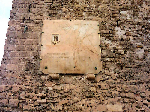
Finally, this is a picture of a real sundial built around 1930 at Tripoli, Libya, I saw recently. Far better than the ones I used to improvise on summertime when I was a kid and didn’t mind melting under the Summer sun.
For questions or comments or anything else, just write, If you build your own, send pictures.
The hex file ready to be burnt into the microcontroller is here, the C source code is here … and the schematic.
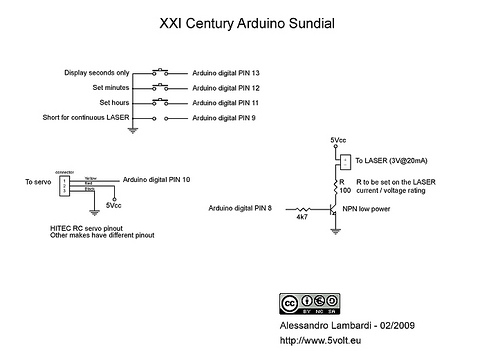
The schematic for Arduino is herebelow, click for a larger view (on Flickr) :