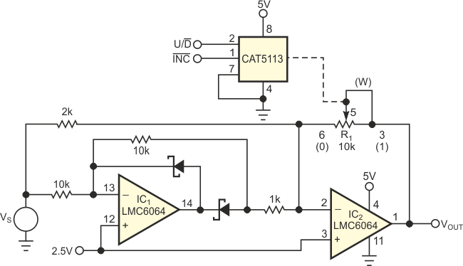
The absolute-value amplifier is a basic building block in test-and-measurement and signal-processing applications. The addition of a DPP (digitally programmable potentiometer) adds another dimension, G (gain), to this key circuit. Because the gain is programmable, you can use the circuit as an absolute-value amplifier (G>1) or an absolute-value attenuator (G<1).
 |
||
| Figure 1. | Attenuate or amplify with this variable-gain absolute-value circuit. | |
The single-supply circuit in Figure 1 comprises IC1, which is an inverting amplifier for positive-polarity signals only, and IC2, the summing amplifier. For the summing amplifier, R1 represents a programmable, variable resistance. This resistance is modeled as

where p varies from 0 to 1/99 to 99/99 and represents the relative wiper setting from one end of the potentiometer (0) to the other end (1). For input voltages above the reference, for example, VS > 2.5 V and for voltages below the reference, VS < 2.5 V,

The potentiometer, a 5113, has 100 taps and an increment/decrement interface. For this DPP, the circuit gain varies from 5/99 to 5. The measured accuracy of the circuit is approximately 1% for moderate values of gain (0.5 to 4) and for a characterized end-to-end resistance, RPOT. During power-up, the wiper goes to its stored value in nonvolatile memory. This stored value establishes the default value of the gain after power-up. The basic idea for this absolute-value circuit came from Reference 1.
