Sometimes, you need to distinguish between two voltages, using some hysteresis in the decision. When the levels of the compared signals vary over a wide range (for example, a few orders of magnitude), the hysteresis width should vary similarly to ensure a constant ratio between hysteresis width and signal level. You could encounter such a situation, for example, when you need to decide which of two transmission channels conveys a “higher quality” signal (one with a higher level). You need the hysteresis to avoid permanent changes in the decision when the signal levels are close to each other. In this case, the best way to choose the greater voltage is to make the decision by taking the ratio of the signals instead of comparing them directly. Figure 1 shows a circuit with signal-variant hysteresis.
 |
|
| Figure 1. | Signal-variant hysteresis allows you to compare signals with a constant-ratio trip window for a wide range of signal levels. |
Amplifiers IC1A and IC1B with associated resistors and diodes, R1, R2, D1, and D2, operate as logarithmic converters, producing output voltages

where

at room temperature, and IS is the saturation current of the p-n junction. The derivation of the equation assumes that R1 = R2 = R. Next, voltages VO1 and VO2 combine in the summing amplifier, IC1C. Using the assumption that R3 = R5 and R4 = R6 and that the diodes are matched, the output voltage from IC1C is

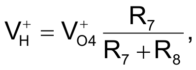
The voltage is thus proportional to the ratio of the input voltages. The last amplifier in the circuit, IC1D, is a standard inverting comparator with hysteresis centered around zero and the threshold levels:

and

The voltage swing at the output of the circuit (V+O4, V–O4), is a function of the limiter comprising resistor R9 and diodes D3 to D8. The output voltage, VO4, changes state when VO3 > V+H (output goes low) or VO3 < V–H (output goes high). These conditions correspond to

or

The design allows you to distinguish between two signals, with a tolerance set by the external components, R3, R4, R7, and R8. When V+O4 = |V–O4|, the tolerance is symmetrical. With the given values, the output state changes when one input signal is approximately 30% higher than the other. If you need to use the circuit over a wide temperature range, you should take the thermal dependence of the threshold levels into consideration. The circuit uses an LM324 quad op amp. If you use a rail-to-rail amplifier the output limiter is unnecessary.
