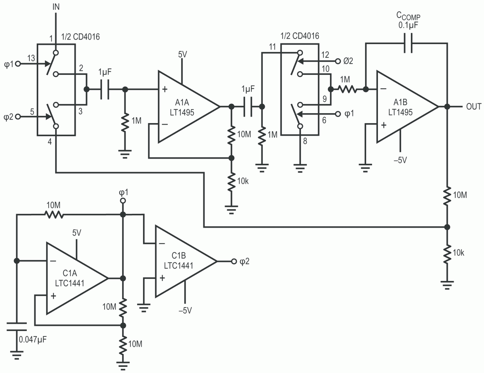
Figure 1 shows a chopped amplifier that requires only 5.5 µA supply current. Offset Voltage is 5 µV, with 0.05 µV/°C drift. A gain exceeding 108 affords high accuracy, even at large closed-loop gains.
 |
|
| Figure 1. | 0.05 µV/°C chopped amplifier requires only 5 µA supply current. |
The micropower comparators (C1A and C1B) form a biphase 5 Hz clock. The clock drives the input-related switches, causing an amplitude-modulated version of the DC input to appear at A1A’s input. AC-coupled A1A takes a gain of 1000, presenting its output to a switched demodulator similar to the aforementioned modulator.
The demodulator output, a reconstructed, DC-amplified version of the circuit’s input, is fed to A1B, a DC gain stage. A1B’s output is fed back, via gain setting resistors, to the input modulator, closing a feedback loop around the entire amplifier. The configuration’s DC gain is set by the feedback resistor’s ratio, in this case 1000.
The circuit’s internal AC coupling prevents A1’s DC characteristics from influencing overall DC performance, accounting for the extremely low offset uncertainty noted.
The high open-loop gain permits 10 ppm gain accuracy at a closed-loop gain of 1000.
The desired micropower operation and A1’s bandwidth dictate the 5 Hz clock rate. As such, the resultant overall bandwidth is low. Full-power bandwidth is 0.05 Hz with a slew rate of about 1 V/s. Clock-related noise, about 5 µV, can be reduced by increasing CCOMP, with commensurate bandwidth reduction.
