Story
The high temperature of the power components is a known phenomenon in electronics. To overcome this challenge, the designers mount heatsinks on the components to dissipate the heat, however, in many commercial and home appliance devices, the embedded heatsink is not adequate and the air must be circulated faster to reduce the heatsink and component temperature, otherwise, the lifetime of the component is reduced significantly.
The proposed automatic FAN controller board is simple, compact, and can be embedded inside commercial devices. The LM35 temperature sensor could be fixed on the heatsink using some silicon glue.
The user can easily set the temperature threshold using a potentiometer. The board can be supplied using a 5 V or a 12 V supply, therefore a variety of 5 V, 12 V, miniature, and PC FANs can be used.
I used Altium Designer 21 and SamacSys component libraries (SamacSys Altium plugin) to draw the schematic and PCB. Except for the connectors, all components are SMD and easy to solder.
Circuit analysis
Figure 1 shows the schematic diagram of the device. The two major components are a temperature sensor and an opamp.
 |
|
| Figure 1. | The schematic diagram of the cooling Fan controller (Altium Designer). |
U1 is the LM358 opamp that is configured as a comparator. If the voltage of the positive input is higher/lower than the negative input, then the output would be close to the VCC/GND. When the temperature of the environment (the voltage on the positive pin) is higher than the pre-set temperature (the voltage on the negative pin), then the output will be activated and vice versa. The LM358 has two opamps. The second opamp is not used and configured as a voltage follower. R2 is a multiturn potentiometer to easily adjust the temperature threshold.
R3 and D2 are used to limit the output voltage of the U1 because the maximum tolerable voltage of the gate pin of Q1 is 8 V, moreover, they help to maintain the voltage of the D3 LED at around 4.7 V, so the value of the R4 is fixed to 470R for any supply voltage. R5 is used to prevent the unwanted triggering of the Q1 gate.
Q1 is the SI2302 N-channel SMD MOSFET that can switch up to 2.2 A continuously, so I decided to use this MOSFET, instead of using a mechanical relay. D1 protects the Q1 against reverse inductive currents and C3 is used to reduce the switching noises. C1 and C2 are bypass capacitors and are used to reduce noises.
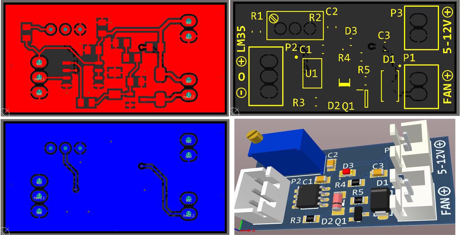
PCB layout
Figure 2 shows the PCB layout of the design. It is a two layers PCB board and except for the connectors, all components are SMD. The board size is 3.8 cm × 1.9 cm.
 |
|
| Figure 2. | The schematic diagram of the cooling Fan controller (Altium Designer). |