Since I wanted to do some USB development work with the PIC18F4550 and PIC18F2550 board (for projects like my C64 VICE front-end and Atari joystick adaptor) I needed a USB reference board to develop the software. Initially I ported the Microchip USB stack over to Hi-Tech C18 pro with the help of Richard Stagg.
In this article I will show how to make your own USB development board which is pin compatible with the Microchip PICDEM USB FS board. Of course you can just buy the original board direct from Microchip, but building it yourself is a far cheaper option.
With this board you can compile and load the Microchip USB stack examples directly without altering the code. You simply need to compile the PICDEM FS USB projects which are included with the stack examples.
Building the PIC DEM FS USB board
The circuit schematics for the original board are available on-line from Microchip, they publish them as part of the user manual for the board. I used the pin-out for the PIC microcontroller, but simplified the design to make it easier and cheaper to make.
Primarily I simplified the power regulation and removed the physical serial port and the serial line driver chip.
Here is the circuit schematic for the board:
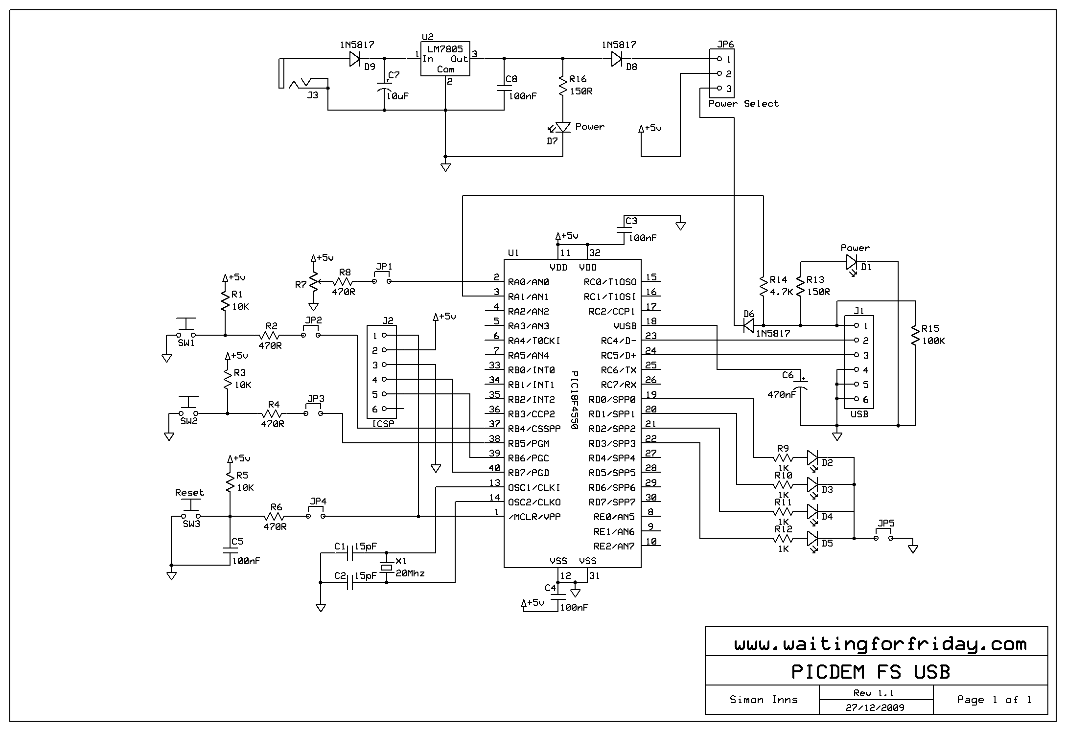
As you can see from the diagram all of the on-board peripherals are connected to physical 'jumpers' allowing them to be turned off. The reason for this is that I intended to put 20 pin SIL connectors on either side of the processor allowing you to easily connect the board to a breadboard. This allows very fast prototyping of USB devices (which actually makes this board far more useful than the original Microchip version).
You can also select between bus-powered and self-powered using a jumper. The board has 5V regulation and polarity protection. Also barrier diodes protect the USB port from unwanted power feedback (to make it a little safer for your PC).
Since I wanted the to be able to make the board myself I needed to design a single-sided PCB which could be easily etched. I also wanted to allow space for 'feet' on the PCB so it can be used without a case (which would make it hard to access the SIL connectors).
Here is the resulting PCB artwork for the board:

Adding a physical RS232 port
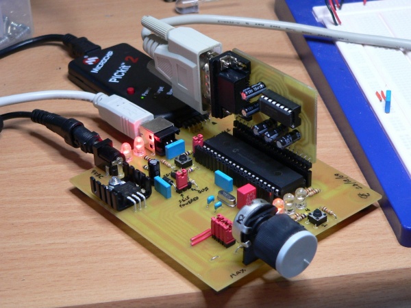
As a pluggable option to this board you can also build a RS232 adaptor which simply plugs in to the right-SIL connector on the processor. Since the UART Tx/Rx and the power lines are available the board is a very simple MAX232 chip with 4 1uF capacitors and one 10uF capacitor.
Here is a picture of the RS232 board connected to the PICDEM FS USB mini board:
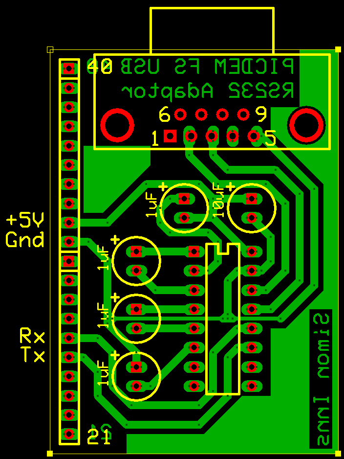
Since the circuit was so simple I didn't make a schematic for it, but here is the resulting PCB Artwork (the component values are marked on the PCB):
PICDEM FS USB RS232 daughterboard PCB Artwork
Files for download
In the following zip file you will find the schematics in ExpressSCH format and also the PCB artwork in ExpressPCB (both pieces of software can be freely downloaded from the Internet):
