Configuring LCD for 8-bit mixed pin mode
To make sure things are working correctly lets set up project for 8-bit mixed mode. To do so we connect LCD as follows:
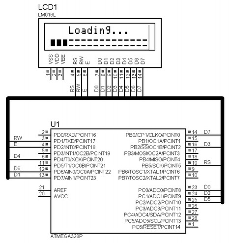
Again we uncomment following mode:
#define LCD_8BIT_M
Then assign pin numbers:
#define LCD_RS 5 //define MCU pin connected to LCD RS
#define LCD_RW 1 //define MCU pin connected to LCD RW
#define LCD_E 2  //define MCU pin connected to LCD E
#define LCD_D0 0 //define MCU pin connected to LCD D0
#define LCD_D1 7 //define MCU pin connected to LCD D1
#define LCD_D2 1 //define MCU pin connected to LCD D2
#define LCD_D3 2 //define MCU pin connected to LCD D3
#define LCD_D4 4 //define MCU pin connected to LCD D4
#define LCD_D5 2 //define MCU pin connected to LCD D5
#define LCD_D6 6 //define MCU pin connected to LCD D6
#define LCD_D7 0 //define MCU pin connected to LCD D7
and finally we chose ports for each pin assigned pin:
#ifdef LCD_4BIT_M || LCD_8BIT_M //
#define LDPRS PORTB //RS pin assignment
#define LDDRS DDRB
#define LDPRW PORTD //RW pin assignment
#define LDDRW DDRD
#define LDPE PORTD  //E pin assignment
#define LDDE DDRD
#define LDPD0 PORTС //D0 pin assignment
#define LDDD0 DDRС
#define LDPD1 PORTD //D1 pin assignment
#define LDDD1 DDRD
#define LDPD2 PORTС //D2 pin assignment
#define LDDD2 DDRС
#define LDPD3 PORTB //D3 pin assignment
#define LDDD3 DDRB
#define LDPD4 PORTD //D4 pin assignment
#define LDDD4 DDRD
#define LDPD5 PORTC //D5 pin assignment
#define LDDD5 DDRC
#define LDPD6 PORTD //D6 pin assignment
#define LDDD6 DDRD
#define LDPD7 PORTB //D7 pin assignment
#define LDDD7 DDRB
#endif
Configuring LCD for normal 4-bit
In case you need to use LCD in byte aligned way like we used to do in old version of LCD library. To do so we need to uncomment mode:
#define LCD_4BIT
We still need to define pin numbers for for control and data pins.
#define LCD_RS 0 //define MCU pin connected to LCD RS
#define LCD_RW 1 //define MCU pin connected to LCD R/W
#define LCD_E 2  //define MCU pin connected to LCD E
#define LCD_D0 0 //define MCU pin connected to LCD D0
#define LCD_D1 1 //define MCU pin connected to LCD D1
#define LCD_D2 2 //define MCU pin connected to LCD D2
#define LCD_D3 3 //define MCU pin connected to LCD D3
#define LCD_D4 4 //define MCU pin connected to LCD D4
#define LCD_D5 5 //define MCU pin connected to LCD D5
#define LCD_D6 6 //define MCU pin connected to LCD D6
#define LCD_D7 7 //define MCU pin connected to LCD D7
Then we only need to define data and control ports as follows:
#if defined (LCD_4BIT) || defined (LCD_8BIT) //if aligned mode
#define LDP PORTD //define MCU port connected to LCD data pins
#define LCP PORTD //define MCU port connected to LCD control pins
#define LDDR DDRD //define MCU direction register for port connected to LCD data pins
#define LCDR DDRD //define MCU direction register for port connected to LCD control pins
#endif
same situation with normal 8 bit mode.
It is obviously that in pin aligned mode LCD update is faster as either 4-bit or 8-bit mode accepts data faster – byte or nibble operation. In mixed mode each individual pin needs to be set separately. This increases number of instructions used to transfer byte. For instance in order to send a byte in LCD_8BIT_M mode I used a helper function:
static void LCDMix_8Bit(uint8_t data)
{
if((data)&(0b10000000)) LDPD7 |=1 LCD_D7;
else LDPD7 &=~(1LCD_D7);
if((data)&(0b01000000)) LDPD6 |=1LCD_D6;
else LDPD6 &=~(1LCD_D6);
if((data)&(0b00100000)) LDPD5 |=1LCD_D5;
else LDPD5&=~(1LCD_D5);
if((data)&(0b00010000)) LDPD4 |=1LCD_D4;
else LDPD4 &=~(1LCD_D4);
if((data)&(0b00001000)) LDPD3 |=1LCD_D3;
else LDPD3 &=~(1LCD_D3);
if((data)&(0b00000100)) LDPD2 |=1LCD_D2;
else LDPD2 &=~(1LCD_D2);
if((data)&(0b00000010)) LDPD1 |=1LCD_D1;
else LDPD1&=~(1LCD_D1);
if((data)&(0b00000001)) LDPD0 |=1LCD_D0;
else LDPD0 &=~(1LCD_D0);
}
LCD_D7;
else LDPD7 &=~(1LCD_D7);
if((data)&(0b01000000)) LDPD6 |=1LCD_D6;
else LDPD6 &=~(1LCD_D6);
if((data)&(0b00100000)) LDPD5 |=1LCD_D5;
else LDPD5&=~(1LCD_D5);
if((data)&(0b00010000)) LDPD4 |=1LCD_D4;
else LDPD4 &=~(1LCD_D4);
if((data)&(0b00001000)) LDPD3 |=1LCD_D3;
else LDPD3 &=~(1LCD_D3);
if((data)&(0b00000100)) LDPD2 |=1LCD_D2;
else LDPD2 &=~(1LCD_D2);
if((data)&(0b00000010)) LDPD1 |=1LCD_D1;
else LDPD1&=~(1LCD_D1);
if((data)&(0b00000001)) LDPD0 |=1LCD_D0;
else LDPD0 &=~(1LCD_D0);
}
Where every bit in data byte is tested and then corresponding port pin is set or reset. Generally speaking if your application simply indicates information that doesn't have to be updated frequently any mode is fine. But if you use LCD for dynamic indication like animations or other fancy way that needs fast LCD update then probably chose normal 8-bit mode or at least 4-bit. If you find errors or difficulties to use this lib, fell free to post a comment.
Downloads
AVR-GCC LCD library with mixed pins modes - download
AVR LCD 4-bit mixed pin mode example - download
AVR LCD 8-bit mixed pin mode example - download