Part 1 - How does RFID work, Whats stored on the card
So the next step was to identify how to pretend to be a card - I wanted a card that I could type a card number into, so it had to have a microprocessor on it, was well as a keypad to allow the data to be keyed in.
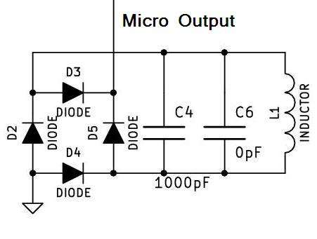
The Atmel ATmega8 manipulates the 125kHz RF field by using a bridge rectifier. When the output of the micro is low, the diodes in the bridge are allowed to be turned on by the current induced in the coil, this effectively short it out. The reader detects the additional load, and a bit transition is detected.
The job of the micro is simply to turn the output on and off in a way that makes sense to our reader. So I created a board that had the micro, a power supply, keypad, and some status LEDs on it.
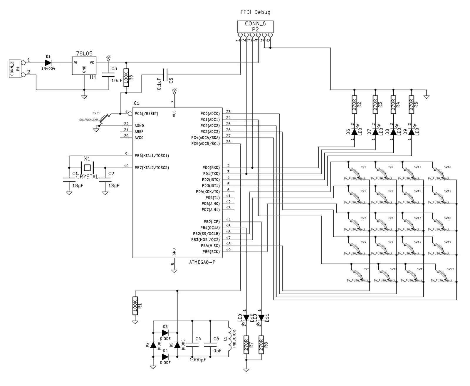
The attached PDF in downlod section is the full schematic of the project.
You may notice that c6 is 0pF - That is intentional c6 is a placeholder component allowing me to either use a 1000pF surface mount cap, or a 1000pF through hole cap. The coil is 100 turns of fine wire would on an open former that is just smaller than the card border.
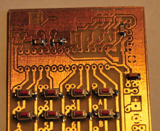
The etched PCB had its edges cleaned up a bit using a file, and holes were drilled for the IC legs. Attached are the PDF files that I used for the Toner Transfer. To keep the project the same size as a normal prox card, I decided to make it on a small PCB that was the same size as a business card.
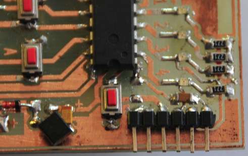
I decided to use surface mount push buttons that I brought from eBay, so that meant that all of the components must be soldered onto the copper side of the PCB to allow the buttons to be mounted and labeled. I started by soldering the push buttons, then I mounted the LEDs, resistors and capacitors. I had to install the 16MHz crystal on the bottom of the PCB, as I did not have a surface mount crystal. I also installed 12 jumpers on the back of the card to connect the key columns together.
The ATMega168 was mounted next. I did not use a socket, as I wanted to reduce the board thickness.
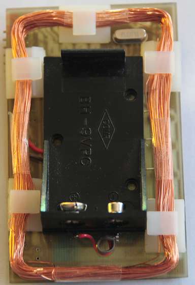
Next, I wound the coil - I used a piece of scrap timber, with 4 screws mounted on it, and counted 100 turns of 0.25mm diameter coil winding wire. Before I removed the coil from the mounts, I wound a small amount of clear tape around each edge to make sure that the coil didn't unwind.
Then, I mounted the coil on the back of the PCB, along with a small battery holder.
Downloads
Schematic and PCB - download
Part 3 - The Software, Entering data into our card
