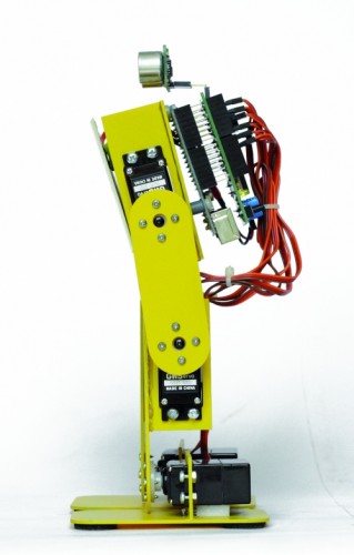
Filippo robot
Filippo is a biped robot whose movements are assigned to only two servos, but with this robot you can experiment with robotics without spending large sums. It is able to walk and turn around, then you can direct it in any direction, enabling those who are beginning to become familiar with the servos and how they can interact with mechanical parts. Its assembly is facilitated because all the pieces fit over each other and it is sufficient sorder to fix them permanently, as an alternative you can use the epoxy glue.
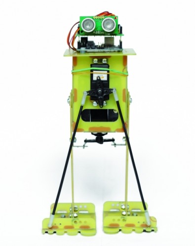
After the mechanical assembly, fix the Arduino board, with its shield, on top, the sensor SRF05 must look in front of the robot. The servos have to be wired as indicated in Table.
Connecting servos with Filippo robot
|
Servo
|
Arduino Pin
|
Connector Shield
|
Function
|
|
Servo 0
|
2
|
S1
|
Tilt (front servo)
|
|
Servo 1
|
3
|
S2
|
Step (servo in the bottom)
|
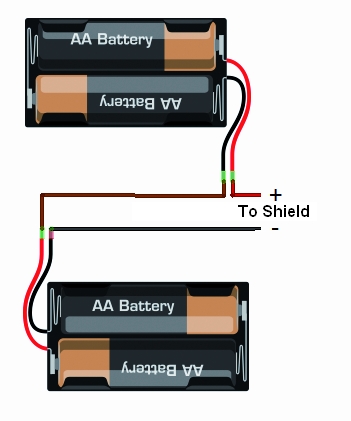
For the power use 6 or 8 NiCd or NiMh rechargeable batteries size AA, they should be entered in two separate holder and connected in series. The battery holder are positioned one on the right and one on the left of the two servos, for their wiring must use two clips for batteries connected in series to 9 V.
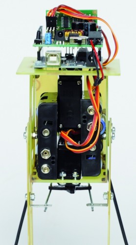
We recommend you to program the Arduino before connecting the servos to prevent any previous program provides the wrong signals to the servos that might go crazy.
Send the serial command ‘obs‘ for read the sensor SRF05 and the command ‘lev‘ to check the battery level. Make sure that the voltage read corresponds to the real value of the batteries, simply make a voltage measurement with a multimeter. Now set the neutral of the servos, in fact the robot to function properly must be perfectly centered. To center the servo which acts to tilt the robot you have to send the command ‘axx‘ where xx is the position. This data can assume values between 80 and 100 with the center point 90, if you can not set the servo to remain within these values you have to physically move the servo. You can modify this value if it found a tendency to deviate from the straight line when walking. Now regulate the step servo and sets the neutral with bxx command, where xx is the position to be allocated (value between 80 and 100). You are now ready for test, you can use the remote control to activate functions or use the button on the shield but it will only start the walk.
All functions have a speed of execution that can be changed by remote control with keys prog+ and prog-, many other parameters can be modified to adapt the software to different operating requirements.
The sketch begins by including the libraries dedicated to the use of the servos, the IR control and management of EEPROM.
The servo library is already implemented in the IDE of Arduino. The EEPROM library, also available, provides controls to manage the non-volatile memory, we use it to save the position of the neutral servos so as not having to set each time.
The third library IRremote is used to manage the robot by remote control and must be downloaded from downloads section, for its operation is sufficient to specify which pin is connected to the sensor receiving IR signals (D10 in our shield). To find out if they arrived from the sensor data must test the status of the variable irrecv.decode (& results), but the code is contained in the variable came results.value.
Just compare the code recived with the reference code for the remote to know which button was pressed, so we specify at the beginning of the sketch of the codes for each button.
Code 2
#define STNB_CODE1 0x81D    // Stop Philips TV remote (STOP)
#define STNB_CODE2 0x1D     // alternative code
#define WALK_CODE1 0x81C    // Play Philips TV remote (WALK)
#define WALK_CODE2 0x1C     // alternative code
#define SPEEDUP_CODE1 0x820 // Prg+ Philips TV remote (+SPEED)
#define SPEEDUP_CODE2 0x20  // alternative code
#define SPEEDDW_CODE1 0x821 // Prg- Philips TV remote (-SPEED)
#define SPEEDDW_CODE2 0x21  // alternative code
#define LEFT_CODE1    0x2C  // Left Philips remote (SX wheel)
#define LEFT_CODE2    0x82C // alternative code
#define RIGHT_CODE1   0x2B  // Right Philips remote (DX wheel)
#define RIGHT_CODE2   0x82B // alternative code
As you can see each button is associated with two codes (CODE1 and CODE2) this is because the codes are sent alternately every time you press the button, instead of repeating the same code if the button is pressed. So if you press the play button will send the code 0x81C and so long as the button is pressed, if you release the button and press it sends the code 0x1C, so alternately.
The sketch is intended for use with remote controls which use the encoding Philips, the most commonly used in television. If you use a different remote control the code of the buttons do not match and you have to change the codes listed above.

Now let’s see what parameters can be modified by the program to adapt the movements:
- TimeOneStep is the initial value of the time taken to perform a step, can be changed by remote control from a minimum of 1 sec to a maximum of 4 sec.
- AmpPasso is the maximum amplitude in degrees of opening of the legs during walking, its value can vary from a minimum of 5 to a maximum of 40.
- IncPasso is the maximum inclination of the robot during the walk, its value can vary from a minimum of 5 to a maximum of 20. This value is to ensure the robot to keep balance on one leg while performing a step.
- AmpRuota is the maximum amplitude in degrees of opening of the legs during the rotation, its value can change from a minimum of 5 to a maximum of 40.
- IncRuota is the maximum inclination of the robot during the rotation, its value can change from a minimum of 5 to a maximum of 20.
ROBOT BIPE
We see now to the second robot, is called BIPE.
The mechanical is made of PCB and assembly is made by soding together the various components to ensure the strength needed to support the weight of the components.
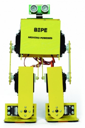
The control board based on Arduino + shield is positioned on the back of the robot while the battery pack, should be placed at the front. Let’s say that for our tests we used a battery composed of two cell 850mAh LiPo which, being small and light, are easily placed and not weigh down the structure. To properly position the sensor SRF05 you must use a small adapter with a strip made of male-female, as those used on the Arduino shield, angled 90 °.
Connecting servos with robot BIPE
|
Servo
|
Arduino Pin
|
Connector Shield
|
Function
|
|
Servo 0
|
2
|
S1
|
Left hip
|
|
Servo 1
|
3
|
S2
|
Left knee
|
|
Servo 2
|
4
|
S3
|
Left foot
|
|
Servo 3
|
5
|
S4
|
Right hip
|
|
Servo 4
|
6
|
S5
|
Right knee
|
|
Servo 5
|
7
|
S6
|
Right foot
|
For setting follow the same instructions for the robot Filippo, the sketch retains the same structure of the software used with Filippo, with the necessary modifications and add.
For this robot is important to the calibration of the neutral of the servos that occurs as previously described. Servo0 corresponds to the letter ‘a‘ – Servo5 corresponds to the letter ‘f‘. If the command is ok will receive confirmation of Serial Monitor, for example: “set servo: a to 90“.
This robot have additional functions such as the bow and football features that are not implemented on Filippo.
To the button ’1 ‘ on Philips Remote Control corresponds to the function of football with which the robot can hit, for example a ball, to the button ’2′ corresponds to the bow that is always of great effect.
The parameters can be set by the program are similar to those of robot Filippo (TimeOneStep, AmpPasso, IncPasso, AmpRuota).
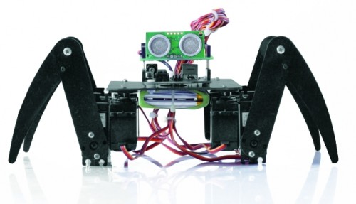
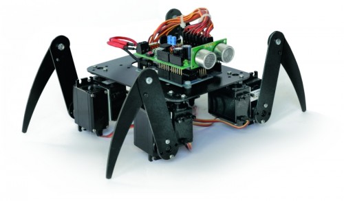
SPIDER ROBOT
With this robot we wanted to replicate the appearance and movements of a spider with all the limitations derived from a simplified mechanics and a limited cost. The choice has been the use of two servos for paw for a total of four legs, which, however, ensure a final result very attractive. The largest number of servos relative to the robot BIPE should not scare because, at the end, this robot is the most simple to make and having regard to the intrinsic stability, does not present serious problems even in the operation. For this robot we have not even provided the adjustment of the neutral servos because of some inaccuracies should not be to influence the operation.The only care is to fix the battery pack in the center so the robots present the center of gravity exactly in the center. During the movement three legs always remain in contact with the ground while one moves, rising, thereby ensuring a good stability.
The mechanical is made by PCB, the same material used for printed electronic and suggest paint it black to improve the aesthetic appearance. No soldering required, and each piece is simply screwed to the servos that make up the mechanics.
How practical advice suggest to program the Arduino board with this program and then electrically connecting the servos, doing so will all be positioned exactly in the middle.Then you connect the mechanical servos in their proper locations.
Make sure that the servos are aligned and that the legs are neither too open nor too closed, taking as reference the pictures posted here.
Connect the servos to the robot Spider
|
Servo
|
Arduino Pin
|
Connector Shield
|
Function
|
|
Servo 0
|
2
|
S1
|
Angle right foreleg
|
|
Servo 1
|
3
|
S2
|
Elevation of right foreleg
|
|
Servo 2
|
4
|
S3
|
Angle of the right hind leg
|
|
Servo 3
|
5
|
S4
|
Elevation of the right hind leg
|
|
Servo 4
|
6
|
S5
|
Angle left hind leg
|
|
Servo 5
|
7
|
S6
|
Elevation of the left hind paw
|
|
Servo 6
|
8
|
S7
|
Angle left foreleg
|
|
Servo 7
|
9
|
S8
|
Elevation of left foreleg
|
Part 3 - Analysis of the firmware, functions that are common to all the robots
Downloads
Gerber files for robots - download