Bipin Duggal
EDN
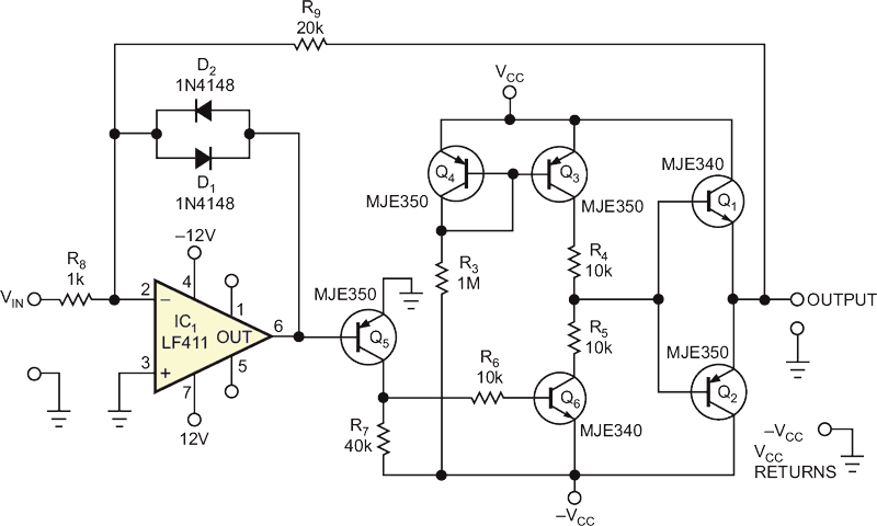
Piezoelectric tubular positioners that drive manipulators in scanning tunneling microscopes require high-voltage, low-current drive circuits. The circuit in Figure 1 can drive high-resistance, low-capacitance piezoelectric loads at a –3-dB bandwidth of 6 kHz. It offers a low-cost alternative to commercial drivers. Transistors Q3 and Q4 form a current mirror, with R3 setting Q4's collector current as the following equation determines:
Operational amplifier IC1 provides base drive to Q5, which in turn drives Q6. With no signal applied to IC1's input, the collector currents of Q6 and Q3 balance, and the output taken from the junction of emitter followers Q1 and Q2 rests at 0 V.
 |
||
| Figure 1. | This complementary-symmetry amplifier features low component count. | |
Applying an input signal to IC1 drives its output toward the positive or the negative 12 V supply rail. Allowing IC1's output to saturate would introduce sufficient slew-rate delay to cause oscillations. Although specifying a relatively fast operational amplifier, an LF411, improves the amplifier's bandwidth and slew rate, antiparallel diodes D1 and D2 improve stability by restricting IC1's output excursion to one diode forward-voltage drop.
 |
||
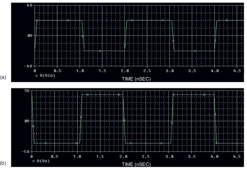
| Figure 2. | The input waveform show input voltage applied as a pulse of –2 to +2 V (a). The output waveform shows an amplifier gain of 20 and minimized output offset (b). |
|
You can adjust R7 to minimize output dc offset voltage and slew rate. As a rule of thumb, select resistor R7 to be twice the value of R9. The ratio of R9 to R8 sets the amplifier's gain. Figure 2 shows the input and output waveforms using optimal values for R7 and R9. Note that the VCEO ratings for Q1 and Q2 limit VCC and –VCC to 300 V or less.