The low-cost composite passive filter in this Design Idea requires no dc power and can enhance the performance of audio equipment and instrumentation by rejecting power-supply hum and spurious pickup from AM, FM, and low-band VHF transmissions (Figure 1). The composite filter comprises a cascade of three simple filters: a T-section highpass filter to reject power-source hum and two π-section lowpass filters to reject spurious RF signals. As a starting point, the three filter sections present a lossless 0.01-dB Chebyshev response at a 50 Ω impedance level, but you can scale the components' values to meet other impedance requirements.
 |
| Figure 1. |
A highpass filter and two lowpass filters help reduce or eliminate
low-frequency hum and high-frequency noise from audio signals. |
| |
| Table 1. |
Components in the prototype filter |
Reference
designators |
Values |
Description |
| C1, C2, C4, C5 |
10 µF |
50 V electrolytic capacitor, ±20% tolerance |
| C3, C6 |
4.7 µF |
50 V electrolytic capacitor, ±20% tolerance |
| C7, C9 |
0.15 µF |
Polypropylene capacitor, ±2% tolerance |
| C8, C10 |
0.033 µF |
Polypropylene capacitor, ±2% tolerance |
| C11, C12 |
0.001 µF |
Polypropylene capacitor, ±2% tolerance |
| L1 |
22 mH |
Inductor, ±5% tolerance |
| L2 |
0.68 mH |
Inductor, ±10% tolerance |
| L3 |
3.85 µH |
Inductor, 27 turns of AWG #28 magnet wire hand-wound
on T37-2 mixture (Carbonyl E) toroidal core |
| S1 |
NA |
DPDT panel-mounted toggle switch |
| J1, J2 |
NA |
50 W BNC panel jack |
| NA |
NA |
Hammond 1590H-BK die-cast aluminum enclosure |
|
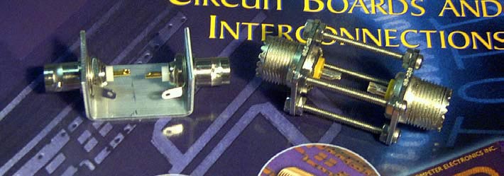
Table 1 lists the components the prototype filter uses. With the exception of inductor L3, all the components are standard values that are available off the shelf. Switch S1 provides a bypass mode that permits rapid frequency-response measurements without connection and disconnection of the prototype's BNC connectors. To construct the prototype, wire all components to a section of perforated breadboard stock supported by metal spacers that mount inside a die-cast aluminum enclosure. This method of shielded construction has proved its worth in other laboratory-accessory applications (Reference 1). Table 2 lists the filter's measured insertion loss over a range of 40 Hz to 200 MHz.
| Table 2. |
Filter insertion loss |
Frequency
(kHz) |
Insertion loss
(dB) |
Frequency
(MHz) |
Insertion loss
(dB) |
| 0.04 |
45.2 |
0.1 |
42.3 |
| 0.07 |
35.4 |
0.3 |
60 |
| 0.1 |
29.4 |
0.5 |
60 |
| 0.2 |
17.3 |
1 |
55.5 |
| 0.3 |
10.9 |
2 |
52.2 |
| 0.5 |
5.5 |
3 |
51.1 |
| 1 |
2.7 |
4 |
56.2 |
| 2 |
2 |
5 |
60 |
| 5 |
1.9 |
10 |
46.5 |
| 10 |
2.1 |
25 |
44 |
| 15 |
2.7 |
50 |
40.5 |
| 20 |
4.5 |
100 |
39.5 |
| 30 |
11.7 |
150 |
45 |
| 50 |
24.5 |
200 |
44 |
|
Low-cost polarized electrolytic capacitors C1 through C6 provide reasonable performance, but observe input polarity for signals with a dc component. For a modest increase in cost and assembly time, you can enhance filter performance and reproducibility by selecting the values of these capacitors to meet a 10% or better tolerance. For best results, use nonpolarized film-dielectric capacitors for C1 through C6. For noncritical applications, you can relax the tolerances for the remaining capacitors and use off-the-shelf inductors for 22-mH L1, 0.68-mH L2, and 3.9-µH L3.
 |
| Figure 2. |
Redesigning the filter to match the 600 Ω impedance that you find in classic audio circuits would increase the inductors' values by an order of magnitude, which would increase the inductors' dimensions and costs. An alternative design approach could use cascaded active-RC filters, which would pave the way for their inclusion into completely integrated composite-audio filters.
Reference