Charles Wenzel
Techlib.com
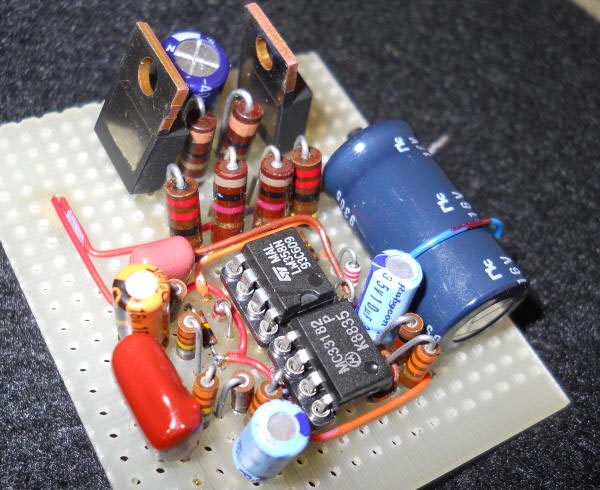
Here's a general-purpose 2 watt audio amplifier with excellent overall performance. It is easily configured to serve as an audio output stage for lower power applications or as a more powerful amplifier for room-filling volume. I've even tried it as an electric guitar "practice" amplifier and with a good speaker it's just about the right power.
The output stage uses a unique technique to stabilize the quiescent current without the traditional temperature-compensating diodes. Each half of IC2 acts as a voltage-follower through its corresponding power transistor, holding the differential voltage across the two 1 ohm emitter resistors to a precise value set by the selected 220 ohm across the inputs. With a 15 volt supply, one can calculate that there's about 16 mV across the 220 ohm in the schematic and the op-amps force that voltage to appear across the two 1 ohm resistors, giving a bias current of about 8 mA (modified slightly by op-amp offset voltages). The quiescent current is easily changed by adjusting that one resistor value for a very low value to conserve battery life or set around 10 mA for the best distortion. Dropping to zero ohms won't hurt anything but might cause noticeable crossover distortion. But too high of a value of resistance will cause the power transistors to get hot and the amplifier will be needlessly inefficient. For lower power applications, say a crystal radio amplifier, higher resistors could be used in place of the 1 ohm emitter resistors with a proportional decrease in the quiescent current. In this way the quiescent current can be dropped to nearly zero with still excellent fidelity – perfect for small battery projects.
The 1N4148 diodes reduce the op-amp output swing when the related transistor turns off; the op-amp only has to swing a diode drop to maintain control over its negative input. Boy, it's tempting to use germanium diodes there! This little trick combined with the full gain and bandwidth of the op-amp being used to simply follow the input voltage results in very low distortion, even at full output and high frequency.
Which op-amps to use
The first two op-amps should be suitable for audio, like the MC33182, LM833 or many, many others. If you see the word "audio" or "distortion" anywhere in the manufacturer's data sheet, it's probably a good choice. : ) Remember that many modern op-amps have low power supply voltage ratings! The gain of those first two stages is set to only 34 each so that even slower op-amps will work fairly well but look for at least 1 MHz GBW. Some perfectly fine op-amps have less output voltage swing than is optimal for this circuit because the output stage has no gain. Less output swing from IC1b means less maximum power but that's usually not a big issue. Don't bother trying the LM358 for the first two stages; that part has a nasty cross-over problem when providing voltage gain.
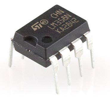
The output op-amp is an LM358. I've had some sort of trouble with every other I've tried! Originally I used faster op-amps here with good results into an 8 ohm dummy load but instability showed up with some speakers due to their reactance. With the LM358 a little distortion is visible as tiny wiggles near zero-crossing at several kHz but the resulting harmonics are mostly above the human hearing range. The phase shift through the TIP31 and TIP32 destabilized the circuit with faster op-amps.
I temporarily lowered the gain of the first stages by bridging the two 33k resistors with 1k resistors. Using a distortion analyzer I measured 0.16% total distortion at 15 to 18 VDC near maximum power. Not bad for an LM358! The distortion dropped to 0.1% while driving 16 ohms with an 18 volt supply. Substituting a 2N2219 and 2N2905 resulted in distortion just under 0.2% with 12 volts.
Which transistors to use
My prototype will operate from 9 volts to 21 volts without any transistor heat sinks using the TIP31 and TIP32. These complimentary TO220 transistors are rated to 2 watts in free air and they will be dissipating about 1.3 watt maximum at 21 volts with an 8 ohm speaker. That's technically okay but they will be quite hot to the touch! Little clip-on heat sinks might be a good idea in this case. For power supply voltages below 18 volts and an 8 ohm speaker, no heat sinks are needed. The maximum power my prototype delivers is approximated by:

(derived from empirical data).
You can use that equation to determine that my prototype delivers a respectable 350 mW into 8 ohms when powered by 9 volts. That's plenty of volume for little radio projects. At the other extreme, the equation predicts 2.5 watts into 8 ohms with a power supply voltage of 21 volts and that's just what I measured at the point of clipping. I used a 1 kHz sine wave for the tests.
Oddly, the stability seems to be relying on the rather low GBW of these power transistors. I tried faster transistors (44H11 and 45H11) but instability near 700 kHz resulted – despite the fact that Spice suggested the opposite would happen! I suspect the faster transistors are just slow enough to add additional phase shift near the unity gain frequency of the LM358 (1 MHz). (Pure guesswork at this point.) Choosing much faster transistors like the 2N2219 and 2N2905 restores the stability, most likely because the roll-off built into the LM358 is "done" by the time the transistors start to shift the phase. Spice agrees in this case. Spice warns that a really slow transistor like the old 2N3055 will be even more unstable. Experimentation is recommended!
Below Vcc = 12 volts the transistor dissipation drops below 350 mW so many small-signal types will work fine without a heat sink.
What problems will I have
This is a lot of gain in a small space and, to make matters worse, there's lots of current flowing in the output stage. Op-amps are quite good at rejecting feedback along the power supply rails and ground but stability can still be an issue. Bring the power and ground from the power supply to the circuit near the output transistors. Connect the input ground near the three 10 µF capacitors and 330 k resistor ground connections. Also note the 1k and 10 µF filter at the input. The amp draws enough power that Vcc will move up and down a bit and letting that signal get back to the input will result in oscillation or, in my case, a mysterious drop in input impedance. That little RC filter prevents that feedback. You can also decide to just use less gain by dropping the 33k resistors or using only one stage of gain. Additional gain could be external to this amplifier.
You can also have stability problems related to the op-amp and transistor choices as explained above, so an oscilloscope is a good idea to make sure the amplifier isn't misbehaving.
A regulated power supply isn't absolutely necessary but at least use a very large capacitor like the 2200 µF shown. Using a three-terminal regulator will add a degree of protection for the transistors in the event the output gets shorted to ground.
What good is it
There are IC audio amplifiers that work as well as this project but not typically. And this circuit uses ordinary parts that most experimenters have on hand. It's easy to change the quiescent current to fit the application and the circuit will work on a wide range of power supply voltages.
Running the circuit on 9 volts makes for a nice general-purpose amplifier for small projects. Switching to the 2N4401 and 2N4403 results in an amplifier similar to the popular LM386 but with adjustable quiescent current and superior distortion at full power.
I just hooked up a guitar and this makes a perfect practice amp! With a good speaker and 18 volts it's surprisingly loud and the sound is quite clean. The preamps as shown provide more than enough gain for a guitar. I'd add a volume control potentiometer across the input, with the wiper going to the 1 µF capacitor. The resistance of that potentiometer will set the input impedance of the amplifier. An audio-taper 10 k pot would be a good choice.
The output section is the meat of this project and it would be fine to drive it with a different front-end amplifier. Just remember that the voltage swing needs to be nearly rail-to-rail to get maximum power since the output stage has no voltage gain.