Gheorghe Plasoianu
EDN
Many applications require positive and negative supply voltages, with only one voltage requiring tight regulation. This Design Idea describes a dual-output, hybrid SEPIC-Ćuk converter whose positive output voltage can be lesser or greater than the input voltage (Figure 1). The unregulated negative output is a mirrored replica of the positive output.
 |
||
| Figure 1. | Dual-output hybrid SEPIC-Ćuk converter. | |
To find out the output voltages we apply the principle of inductor volt-second balance and capacitor charge balance. To simplify the calculus, we neglect the voltage drop over the MOSFET and diode and we consider only continuous conduction mode.
 |
||
| Figure 2. | Equivalent circuit in switch on-state. | |
When the MOSFET is on we have this equivalent network, shown in Figure 2, and the inductor voltages and capacitor currents for this interval, using small-ripple approximation, are:
When the MOSFET is off we have this equivalent network, shown in Figure 3, and the inductor voltages and capacitor currents for this interval are:
Equating the average inductor voltages and capacitor currents over one switching period to zero, we get:
where D is the duty cycle.
 |
||
| Figure 3. | Equivalent circuit in switch off-state. | |
Solving for V4 and V5:
In practice, due to the feedback, the positive output voltage, V4, is fixed.
Extracting the duty cycle from the V4 equation and inserting it into V5 results in:
Therefore, this topology is most suitable when the output currents do not differ much.
When the two loads are equal, then:
and
A variation of the topology can supply a “floating” load is shown in Figure 4.
 |
||
| Figure 4. | Feedback modification for ungrounded load. | |
The op-amp converts the differential output voltage to single-ended for regulation. The differential output voltage is:
For Figure 4:
where VFB of the LM3488 is 1.26 V.
I measured VOUT = 18 V for RL = 47 Ω, and 18.02 V with a 94 Ω load. That gives a load regulation of about 0.1 V/A, or 0.55% of VOUT.
 |
||
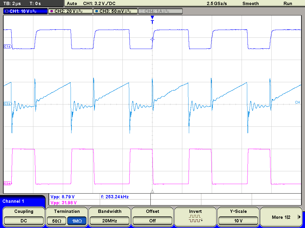
| Figure 5. | MOSFET waveforms. | |
Figure 5 shows the gate, source, and drain voltages of the MOSFET. The duty cycle is about 60%.
