This is versatile development board for AVR microcontrollers ATmega48/88/168. It is good for testing and debugging embedded programs. It has many built-in peripheries connected to microcontroller so you can use them without soldering. ATmega microcontrollers are produced by ATMEL and they include a lot of features: I/O, Timers, PWM generators, ADC, RS232, TWI, SPI, Analog Comparator, Oscillator, EEPROM… These microcontrollers are very versatile, easy to program and easy to use. This is the reason why I like these microcontrollers and why I decided to make development board for them.
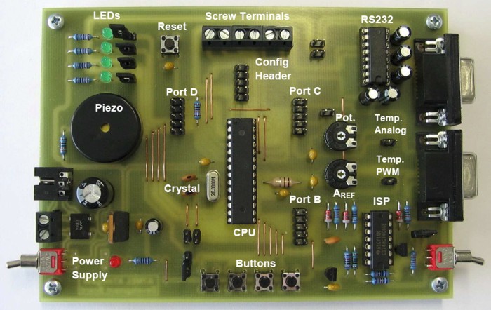
Top View
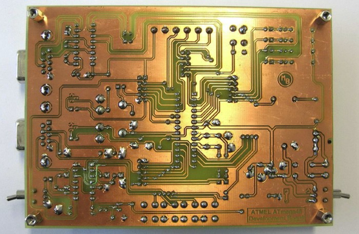
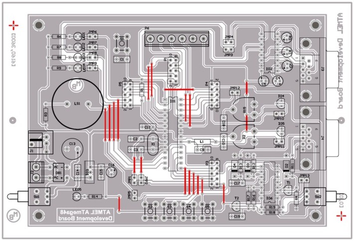
Bottom View
The development board is designed to use ATmega48 with 4kB flash memory or ATmega88 (8kB), ATmega168 (16kB). New version of these microcontrollers ATmega48P/88P/168P and ATmega328P (with 32kB) are pin compatible so they can be used also.
External crystal X1 is placed in socket, so it is easy to change it or remove it. If internal oscillator is used then two PB6 and PB7 pins dedicated for crystal can be connected to the Port B connector. Microcontroller can be reset by pressing reset button S1.
If built in peripheries are not used another device can be connected to the PORT B, C and D. Each port is connected to the 10-pin header. You could connect LCD display, Rotary Encoder, SD Card Reader, etc. with microcontroller. See my future posts.
Both AC and DC voltage can be plugged in, because of using rectifier bridge. Input voltage can be connected to 2.5mm power jack connector or screw terminal. Power can be switch on / off by SW1. Power supply voltage is stabilized by common IO 7805. When the power is switch on red LED6 is lighted.
Four green LEDs can be connected to the Port D shorting jumpers JMP6-9.
Four buttons are connected to the Port B
Piezo speaker can be connected to pin PB1 through JMP5.
The microcontroller has built-in 10bits AD converter. On the board is LC filter for power supply of this ADC. You can use internal or external reference. The rotary trimming resistor R2 is connected to Aref input for playing with the external reference.
For simulation of varying ADC input voltage the rotary trimming resistor R1 can be connected to PC1 (ADC1) through JMP12.
If you want to play with temperature sensor, you can connect temperature sensor with either analog or PWM output. Temperature sensor with analog output can be connected to the PC0 (ADC0) through JMP10. Temperature sensor with PWM output can be connected to the PB0 through JMP11.
Standard serial interface is placed on the board. Level shifter MAX232 is used. MAX232 has two receiver and two transmitter lines. You can connect RXD and TXD of RS232 with RXD and TXD of microcontroller with help of config header. RTS and CTS of RS232 can be connected with PD6 and PD7 through JMP3 and JMP4. See config header part.
Config header allows interconnect different I/O microcontroller pins with RS232 line or with screw terminal.
Screw terminals allow easily connect wires to microcontroller. Through this terminal you compose for example frequency counter of voltmeter, etc. Ground and 5 Volts are also presented on screw terminal.

Development board includes serial port interface to allow direct in-system programming (ISP). Microcontroller can be programmed trough RS232 serial port by using program Pony Prog or AVDdude (ponyser). To avoid interference with RS232 signals, programmer can be disconnected using analog switches 4066. These switches can be closed manually by SW2 or automatically when the reset is active (using JMP13).
In each corner of PCB is placed one ø3.2mm mounting hole.
Download PCB in PDF or EPS format
Download PCB in PDF
