Charaf Laissoub, France
If you have a pin-limited PIC microcontroller, you can still produce a seven-segment display
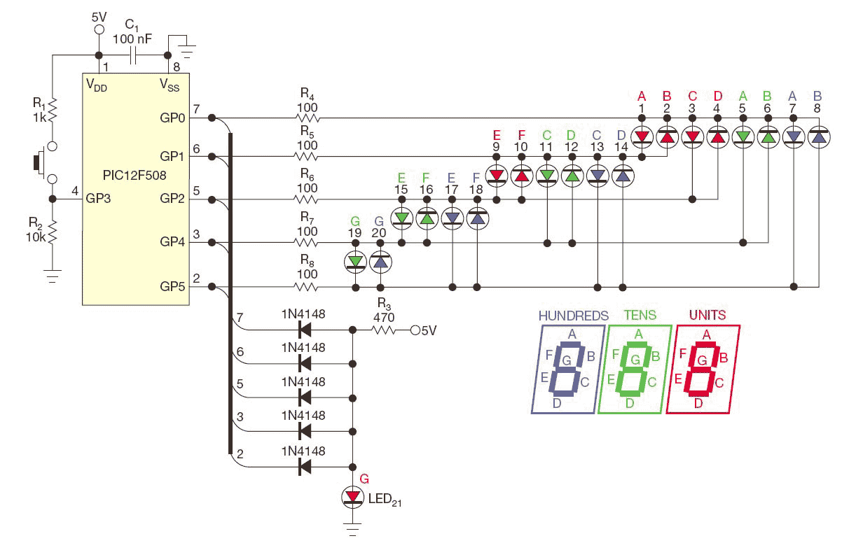
When you need to drive three seven-segment LED displays, you typically need 10 I/O lines—and that’s without a decimal point. You might think that you cannot accomplish that task without a binary-to-seven-segment decoder or a serial-to-parallel shift register. This Design Idea shows how you can build a circuit that drives 21 LEDs, thus forming three pseudo-seven-segment displays.
Figure 1 shows this circuit, and Listing 1 comprises the assembler code. It can also suit any of a Microchip baseline or midrange PIC microcontroller’s eight pins.
 Click to enlarge |
||
| NOTES: | R1 IS OPTIONAL BECAUSE GP3 IS AN INPUT-ONLY PIN. OTHERWISE, IT IS SAFER TO PUT R1 WHEN USING A TRUE I/O LINE AS INPUT. USE 21 SUPERBRIGHT FLAT LEDs, ARRANGED AS A THREE-DIGIT PSEUDO-SEVEN-SEGMENT DISPLAY. |
|
| Figure 1. | An eight-pin microcontroller can drive three seven-segment LED displays. | |
You can adapt this code for another type of microcontroller, such as those from Atmel or STMicroelectronics, using the following steps:
- Build a look-up table of 10 values for seven-segment coding (see table “Code7Segment” in Listing 1).
- Build a look-up table of 3×7 values to store the successive configurations for I/O lines, each configuration containing only one high output and one low output to drive one LED at a time, for each digit (see table “Cfg2LinesOut” in Listing 1).
- Build a look-up table of 3×7 values to store the successive high and low state for the I/O lines that are acting as outputs to light only one LED at a time for each digit (see table “Light1LED” in Listing 1).
- The subroutine DispDigit rotates to the right seven times, through Carry flag, and the seven-segment code of a digit. It then calls the subroutine LEDon each time you set Carry.
- The subroutine LEDon activates the LED related to the I/O configuration code, which you can extract from table “Cfg2LinesOut”, and lights it according to the high or low state code, which you extract from table “Light1LED”. The subroutine ends by a jump to a critical 1- to 3-msec delay subroutine. Increasing this delay increases the flicker effect, and decreasing this delay dims the LED.
- Cycle digits of units, tens, and hundreds through steps 4 and 5.
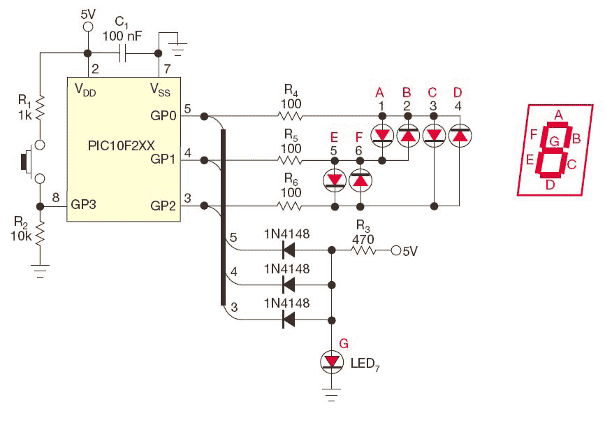
For the PIC10F2xx series, which contains only three I/O lines, Figure 2 shows an example of driving one digit, and Listing 2 shows the corresponding assembler code.
 |
||
| NOTES: | R1 IS OPTIONAL BECAUSE GP2 IS AN INPUT-ONLY PIN. OTHERWISE, IT IS SAFER TO PUT R1 WHEN USING A TRUE I/O LINE AS INPUT. USE SEVEN SUPERBRIGHT FLAT LEDs, ARRANGED AS A PSEUDO-SEVENSEGMENT LED DISPLAY. |
|
| Figure 2. | The PIC10F2xx series microcontrollers can drive a seven-segment display with three pins. | |
