Charaf Laissoub
Replace classical counters with a microcontroller.
A classical design for directly driving eight seven-segment LED displays requires as many as 15 I/O lines. Previous Design Ideas have described many approaches for using a maximum number of LEDs with a minimum number of I/O lines (references 1 through 5). The following idea reuses one of these approaches to drive a maximum number of seven-segment LED displays, and it may be useful in designing a lowcomponent- count, low-power, and lowcost LED-display module for a 24-bit frequency meter, for example.
You can use the circuit in Figure 1 to replace classical designs for digital counters that use TTL (transistor-transistor logic) or CMOS ICs. The single microcontroller PIC16F628A is less expensive and readily available. By using conditional assembly in your programming, you can choose between common-anode and commoncathode configurations.
|
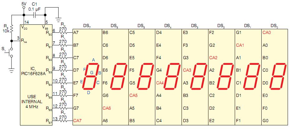
Figure 1.
|
This circuit can replace classical designs for digital counters that use TTL or CMOS ICs.
|
The algorithm uses double multiplexing, driving one digit at a time, segment by segment. This technique suits battery-powered designs because the circuit consumes a constant current of less than 2 mA when using superbright, seven-segment LED displays, such as KingBright’s SC52-11EWA, and 270Ω resistors R0 to R7. Assembling the eight digits, DS7, DS6, DS5, DS4, DS3, DS2, DS1, and DS0, on a PCB (printed-circuit board) involves linking their corresponding pins A7, B6, C5, D4, E3, F2, G1, and CA0 to the I/O line, RB0. Figure 1 shows the connections.
This circuit uses the Microchip PIC16F628A for test purposes. You can use this assembly code with any PICmicro midrange family, providing that a full 8-bit port is available.
