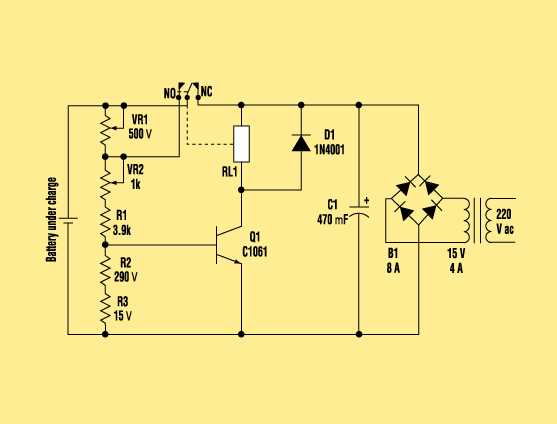
The following automatic battery-charger design is created with a circuit that could qualify as the simplest window comparator ever built around a single transistor. It starts charging when the battery voltage drops beyond a preset value, and it stops when an upper preset voltage is attained. With the help of a precise variable voltage supply, the upper and lower voltage levels were set. The normally connected (NC) lead of the relay isn't joined to the 15-V dc supply, which blocks this voltage from passing to the battery leads. This will accurately set the upper and lower levels. But the charging supply of 15 V dc was connected to the circuit.

First, the variable supply is fixed at 13.3 V dc—the voltage of a fully charged battery—and linked to the battery point of the circuit. The slider of VR1 is turned to the extreme end on the side that's attached to the positive terminal of the battery. VR2's slider should be turned toward the end that's connected to VR1. The transistor turns on, shunting VR1. Then the slider of VR1 is turned toward the other extreme, which is the end connected to VR2.
The test supply voltage is now set to 11.8 V dc, which is the voltage of a drained battery. VR2 is then adjusted so that it just turns off the transistor again. The test voltage is raised to 13.3 V dc again, and VR1 is adjusted so that the transistor turns on. With the upper and lower levels set, the NC point is connected to the circuit (15-V dc charging voltage). Now the battery charger is set and ready to go.
