By Jim Wilson Allied Healthcare Products
Electronic Design Europe
Most microcontrollers have a pulse-width modulator (PWM) output that can effectively drive variable output loads such as proportional solenoid valves, motors, or light dimmers. You control these loads by using the PWM basically as a digital-to-analog converter (DAC). You set the duty cycle in the PWM register (digital) and, with a couple of components on the PWM output pin acting as an integrator, you generate a dc voltage output (analog). The analog voltage is proportional to the value in the duty cycle register and ranges from the PWM’s logic low to logic high voltages.
In many applications, however, the device this PWM driver is controlling doesn’t operate over the PWM’s full output voltage range. A motor, for instance, may not turn at all when the drive is below 2 V or a proportional valve may be fully open at 4 V. If your PWM’s logic outputs range from 0 to 5 V, some of the resolution in your PWM is wasted. With the valve, for instance, an 8-bit PWM provides 256 control settings but only about 200 would be useful.
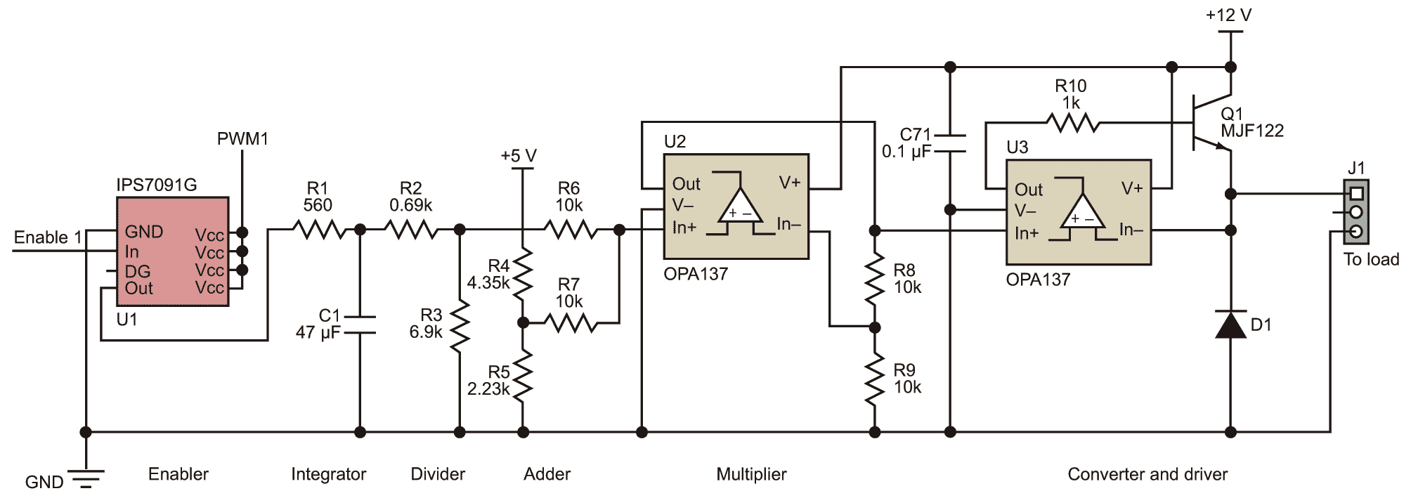
To control devices with the finest resolution possible, you can use some simple textbook analog circuitry and a little trial and error to match the PWM driver to whatever voltage range the device needs. The circuit shown in the figure has six stages, some of which you may not need and can simply leave out:
Enabler
The switch U1 allows selection from among several devices needing control. In the applications that generated this idea, multiple valves and pumps all share one PWM line. The Enable line lets each device be turned on and off individually.
Integrator
This stage of the circuit (R1 and C1) converts the square wave of the PWM to a dc level proportional to the PWM’s duty cycle. The type of capacitor used for C1 affects the speed at which it can charge and thus convert the PWM pulse train to a nice, flat dc level. My application found success with both electrolytic and ceramic capacitors.
Divider
Resistors R2 and R3 form a simple voltage divider that determines the upper limit of the circuit’s output control voltage. For instance, my processor runs on +5 V and thus the PWM output switches 0 to +5 V. The valve I use is fully open when driven at about 4 V. Without this voltage divider stage, 20% of the PWM’s resolution capacity would be wasted as the PWM driver can achieve nothing useful when its output ranges from 4 to 5 V.
Adder
There are many cases in which the low end of the PWM driver’s output isn’t useful. Motors, for instance, usually don’t start running until the drive voltage reaches some minimum threshold. To raise the starting point of the PWM driver’s output range, R4 and R5 form another voltage divider that should be set to a little bit below the desired minimum output. If your motor doesn’t start up until the driving voltage reaches 2 V, you might want to set this voltage divider so R7 sees about 1.8 V. With this scheme you would be only wasting about 0.2 V or 4% of your PWM’s control range rather than 2 V or 40%.
Multiplier
Often the control voltage that the PWM driver produces (5 V in this circuit) is lower than the hardware’s drive needs (12 V here). A multiplier is a simple way to increase the driver’s output voltage to whatever range is required. The values of R8 and R9 determine the multiplication factor. In the figure, R8 and R9 are equal, creating a voltage doubler. For other multiplication factors, use the formula:
![]()
where VO is the output of U2 and VI is the voltage at the IN+ input of U2.
Converter and driver
U3 here is used to convert the PWM driver output voltage to a current and to help reduce variance in the PWM’s control output due to temperature swings. Inductive loads like motors and valves, for instance, generally have a big coil of wire in them, and this wire’s resistance can change with temperature. The voltage follower U3 helps compensate for such changes. During testing of the circuit, the Texas Instruments OPA137 op amp shown proved to be very stable and to perform much better than anything else in its class. D1 is a freewheeling diode used to eliminate the sudden voltage spike seen across an inductive load when its supply voltage is suddenly reduced or removed. Both SK32 and LL4148 diodes have proven effective in various applications.
When using this circuit, optimizing the resistor values for the specific application may take a little trial and error. To simplify the process, use potentiometers so you can adjust them to find the best values, and then replace them with fixed resistors.
Once set up properly, a scheme like this can improve the fineness of control the PWM driver provides. Instead of having only 20% to 40% of the output range be useful, you can have something more like 90% for the cost of just a few inexpensive components.
When using a PWM to produce an analog control voltage for such things as motors and proportional valves, this circuit allows you to shift and scale the control voltage range to match the load’s needs.

