Part 1 - Theory and Schematic
Operation of the board
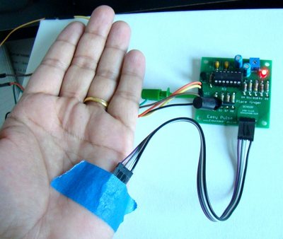
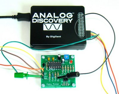
The operation of the board is very simple. After powering the board from a 3-5.5 V supply, the Enable (EN) pin must be pulled high to activate the IR sensor. Next, place the tip of your forefinger gently over the sensor on its face. Your finger should be still and should not press too hard on the sensor. Within a couple seconds the circuit stabilizes and you will see the LED flashing synchronously with your heart beat. You can feed the output signal (Vout) to either a digital I/O or an ADC input pin of the microcontroller for measurement of the heart beat rate in BPM. The output voltage waveform can also be viewed on an oscilloscope. I connected Digilent’s Analog Discovery tool to check the input PPG and the output waveforms from the two LPF stages. The following pictures show these signal waveforms as displayed on the PC screen when.
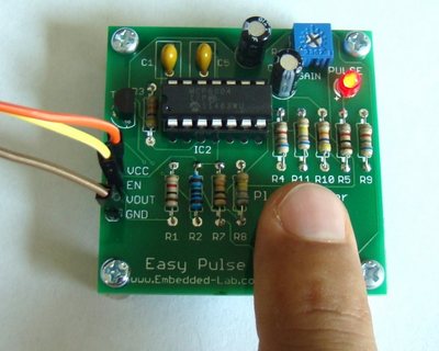
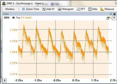
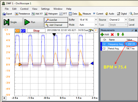
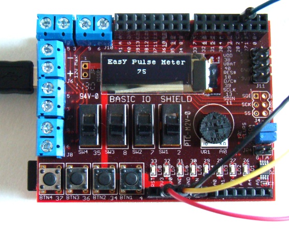
The Easy Pulse output signal can be connected to a digital input pin of Arduino or ChipKIT board to find its frequency. If you multiply the frequency by 60, you will get the heart rate in BPM. I have written a demo code for chipKIT Uno32 and IO Shield to display the heart rate on the OLED. The VCC, EN, VOUT, Gnd pins on the Easy Pulse board are connected to 3.3 V, 5.0 V, Pin 2, and Gnd pins of the I/O shield, respectively.
Download the demo chipKIT sketch
Demo video
Easy Pulse kit on sale
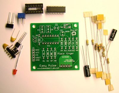
I have made 20 PCBs of Easy Pulse board using iTeadStudio’s 5cm x 5 cm double layer PCB service and I am giving out 15 of them in the form of kits including all the parts required to assemble the board. For those who are interested to try Easy Pulse, the price per kit is $18.00 including the shipping cost within the United States. I will accept payment through Paypal only. You have to email me first at admin (at) embedded-lab (dot) com and I will then send you my Paypal ID. Once I get the payment, I will mail your package through regular USPS (usually takes 3-5 business days). This kit can also be purchased from Tindie. The following picture shows all the parts that are included in the kit.
If you want the sensor to be separate from the board as described earlier, you will need a wire to connect it to the board. The picture below shows a proper way of connecting the sensor to the board using a 4-pin jumper wire. Since the pins or legs of the TCRT1000 are thinner than the holes in the jumper wire, you may need to thicken them a little bit through soldering so that it is hold tight.
Summary
Easy Pulse provides a reflective IR sensor with necessary instrumentation circuit to illustrate the principle of photoplethysmography as a noninvasive technique for measuring heart rate. In order for this sensor to work, the fingertip should be placed gently over the sensor and be kept still. The sensor may also be wired to the board through a 4-pin jumper and header pins. This gives more flexibility of using the sensor as you can place the sensor over the skin on palm, or wrap around a fingertip using paper or duct tape. A more practical way of putting a sensor would be in the form of a finger clip, like in commercial Pulse Oximeters, so that the sensor performance would not be affected too much by a slight movement of the finger.
