Measurement of average power in a 60 Hz circuit (equivalent to VRMS × IRMS × cos(φ)) can be done by sampling the product of voltage and current and averaging. This requires four quadrant multiplication since the instantaneous voltage and current can have opposite polarities. It can be accomplished by a number of means, including analog to digital (A/D) conversion followed by digital signal processing, or by using a relatively expensive analog multiplier chip followed by analog or digital processing. This Design Idea presents a third approach (Figure 1). It uses inexpensive op-amps and an analog switch to implement a pulse width/pulse amplitude modulator (PWM/PAM) used as a four quadrant multiplier. This circuit can be adapted to many different applications.
 |
|
| Figure 1. | Measure AC power using pulse modulation techniques. |
The basic concept of a PWM/PAM multiplier is that the average value of a (non-overlapping) pulse waveform over a single cycle is the area of the pulse divided by the pulse repetition period. With each rectangular pulse amplitude proportional to voltage, and width proportional to current, the area of the rectangle is proportional to the product: voltage times current. If the pulse repetition rate is much higher than the frequency being measured, it can be assumed that the voltage and current do not change appreciably during one cycle of the pulse waveform. The PWM/PAM output is followed by a low-pass filter to remove the pulse frequency and its harmonics and recover the desired average.
The circuit uses two transformers: a step-down transformer TR1 to produce a low-level voltage signal, and a current transformer TR2 to produce a low-level current signal with full galvanic isolation.
Op-amp IC1-A acts as a comparator and generates a fairly linear triangular waveform (Figure 2) with a frequency of about 6 kHz. This over-sampling (100 times the 60 Hz signal frequency, or 50 times the theoretical Nyquist rate) is required to achieve an error below 1% of full scale. The triangle wave peak-to-peak amplitude must meet two criteria for an acceptably linear response. First, it must be greater than or equal to the AC current maximum peak-to-peak voltage from T2 so that a 100% PWM duty cycle is possible. Second, it must be at least 10% less than ±VCC.
 |
|
| Figure 2. | IC1-B (-) input. |
Op-amp IC1-B is configured to generate a zero-baseline bipolar square wave (Figure 3) with duty cycle determined by the instantaneous value of the current signal from T2. Capacitor C2 is required to obtain sharp output voltage transitions. The op-amps should be capable of a slew rate of 10 V/µs or more to produce an optimal square PWM signal. When the instantaneous value of the current signal from T2 is zero, the duty cycle at IC1-B’s output will be 50%. As the current signal increases from zero to full scale, the duty cycle increases from 50% to 100%. As the current signal decreases from zero to negative full scale, the duty cycle decreases from 50% to 0%.
 |
|
| Figure 3. | IC1-B output. |
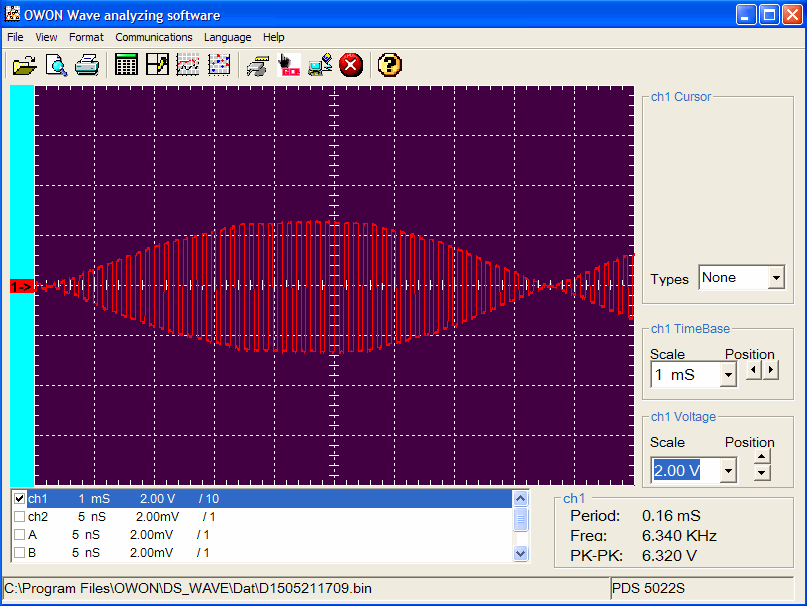
Op amp IC2-A, switch IC3-A, and the associated resistors implement a four-quadrant multiplier (reference 1) in the form of an amplifier with a gain of either +1 (switch closed) or –1 (switch open). The switch is controlled by the PWM output from IC1-B; the switch is closed when IC1-B’s output is positive and open when IC1-B’s output is negative. The resulting output from IC2-A (Figure 4) is a replica of the PWM output from IC1-B (duty cycle proportional to current), except with amplitude proportional to voltage.
 |
|
| Figure 4. | IC2-A output. |
IC2-B, the final stage of the circuit, is a low-pass filter which removes the 6 kHz PWM frequency and its harmonics as well as the 60 Hz modulation. Its output is proportional to the average of the PWM signal, and thus the average 60 Hz power.
References:
- Maxim Integrated, App. Note 4502, “Single IC PWM Modulator has 2% Linearity”, Ahmad Ayar, Aug 10, 2010.
- Maxim Integrated, App. Note 4281, “Advanced Power Line Monitoring Requires a High Performance Simultaneous Sampling ADC”, Joseph Shtargot, Sept. 26, 2008
- EDN Design Ideas, “Two IC-Circuit Combines Digital and Analog Signals to Make Multiplier Circuit”, Rick Mally, Jan. 2013
