Don Sherman, Maxim Integrated Products
EDN
With the aid of a simple mounting system and some soldered-on weights, a piezoelectric “bender” can detect mechanical shocks. The bender comprises a piezoelectric-ceramic element bonded to a thin brass disc. Such assemblies form the heart of many telephone annunciators and wrist-watch or panel-mounted alarms.
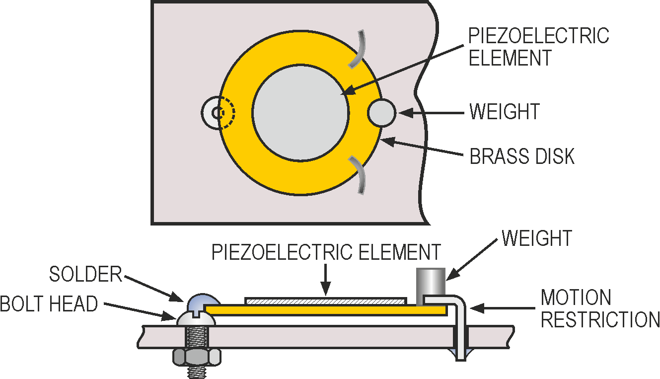
Depending on the mounting scheme, the bender can sense shocks in one axis (Figure 1a) or three axes (Figure 1b). For one-axis sensing, solder one edge of the bender to a mounting bolt. Opposite the mounting bolt, solder a weight to increase the bender’s sensitivity. A small hook affixed to the mounting substrate limits motion so that the brittle piezoelectric element will not crack.
|
||||||
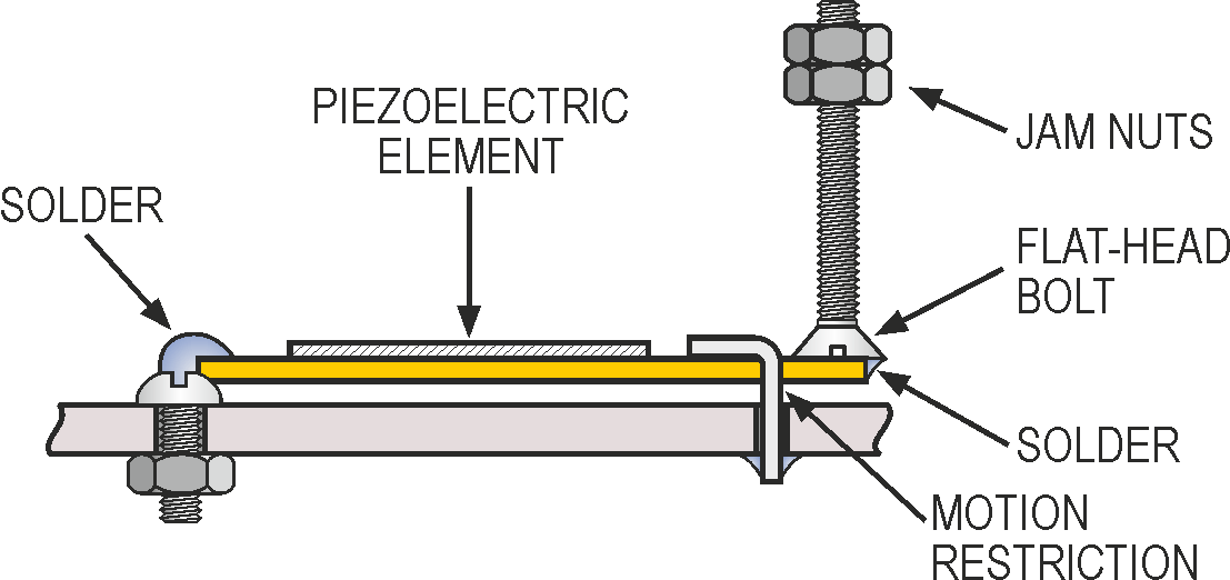
| Figure 1. | Solidly mounting one end of a piezoelectric “bender” and affixing a weight to the opposite edge transforms the bender into a shock sensor. Here, “a” is sensitive to vertical-axis shocks only; “b” senses shocks in all three axes. |
|||||
For three-axis sensitivity, solder one edge to a mounting bolt as before. At the other edge, solder a flat-head bolt that points away from the mounting substrate. Use a pair of jam nuts to increase the assembly’s polar moment of inertia. The jam nuts’ position determines the bender’s sensitivity.
In both cases, apply your soldering iron as briefly as possible to the bender to avoid damaging the piezoelectric element’s bond to the brass disc.
 |
||
| Figure 2. | The circuit sounds a 1-sec alarm whenever you give the bender a good smack. | |
Figure 2 shows a simple alarm circuit. Giving the bender a good smack will develop several volts across R1, the 10-MΩ resistor. The dual-timer IC, IC1, will then pulse the output alarm for one minute at a 1-Hz rate. The alarm has its own driver circuit and sounds a piercing 90-dB tone when energized.


