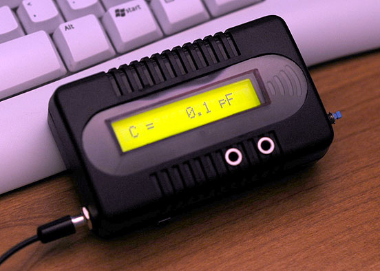
This is one of the most accurate and simplest LC inductance / capacitance Meters that one can find, yet one that you can easily build yourself. This LC Meter allows to measure incredibly small inductances starting from 10 nH to 1000 nH, 1 uH to 1000 uH, 1 mH to 100 mH and capacitance from 0.1 pF up to 900 nF. LC Meter's circuit uses an auto ranging system so that way you do not need to spend time selecting ranges manually. Another neat function is the "Zero Out" switch that will reset the initial inductance / capacitance, making sure that the final readings of the LC Meter are as accurate as possible.
|
|||||||||
|
About LC Meter
This is one of the most accurate and simplest LC inductance / capacitance Meters that one can find, yet one that you can easily build yourself. This LC Meter allows to measure incredibly small inductances starting from 10 nH to 1000 nH, 1 uH to 1000 uH, 1 mH to 100 mH and capacitance from 0.1 pF up to 900 nF. LC Meter's circuit uses an auto ranging system so that way you do not need to spend time selecting ranges manually. Another neat function is the "Zero Out" switch that will reset the initial inductance / capacitance, making sure that the final readings of the LC Meter are as accurate as possible.
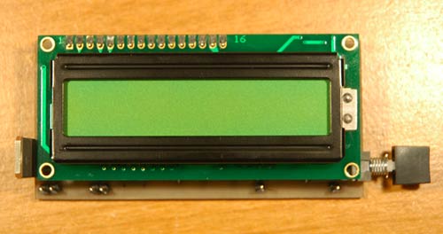
LC Meter Kit with Green Backlight LCD Display

How does LC Meter Work?
To be able to determine the value of an unknown inductor / capacitor we can use the frequency formula given below.

Note that there are three variables that we can work with; f, L and C (f represents a frequency, L inductance and C capacitance). If we know the values of the two variables we may calculate the value of the third variable.
Lets say we want to determine the value of an unknown inductor with X inductance. We plug X inductance into the formula and we also use value of a known capacitor. Using this data we can calculate the frequency. Once we know the frequency we can use the power of the algebra and rewrite the above formula to solve for L (inductance). This time we will use the calculated frequency and a value of a known capacitor to calculate the inductance.
Isn't this amazing? We just calculated the value of unknown inductor, and we may use the same technique to solve for the unknown capacitance and even frequency.
Applying the Theory to LC Meter's Hardware
Now let's use the above theory and apply it to electronics. The LC Meter uses a popular LM311 IC that that functions as a frequency generator and this is exactly what we need. If we want to calculate the value of an unknown inductor we use a know Ccal 1000 pF capacitor and the value of an unknown inductor. LM311 will generate a frequency that we can measure with a frequency meter. Once we have this information we can use the frequency formula to calculate the inductance.
The same thing can be done for calculating the value of a unknown capacitor. This time we don't know the value a capacitor so instead we use the value of a known inductor to calculate the frequency. Once we have that information we apply the formula to determine the capacitance.
All this sounds great, however if we want to determine the value of a lot of inductors / capacitors then this may become a very time consuming process. Sure, we can write a computer program to do all these calculations, but what if we don't have an access to a computer or a frequency meter?
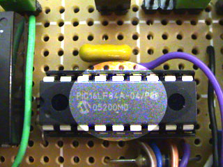
That's were PIC16F84A microchip comes handy. PIC16F84A is like a small computer that can execute HEX programs that are written using an assembly language. PIC16F84A is a very flexible microchip because it has PINs which can be configured as inputs and outputs. Besides that, PIC16F84A IC requires very minimal number of external components like 4 MHz crystal / resonator and few resistors depending on what project we are building. Before we can use PIC16F84A microchip we have to program it with a HEX code which has to be sent from the computer.
In the next step we use the frequency generated by LM311 IC and pass it on to PIC16F84A's PIN 17. We designate this PIN as an input, as well as all other PINs that are directly connected to switches and jumpers. User can use these inputs to tell the microchip to execute specified set of instructions or perform calculations.
Once the microchip will calculate the unknown inductance or capacitance it will use PINs that are designated as outputs and pass the results on to the 16 character LCD display.
LC Meter's Switches & Jumpers
SW1 - Zero out the readings.
SW2 - Capacitance / Inductance switch.
J3 - turns on the backlight on LCD displays that have LED backlight.
J1 - used by 16x2 two line character LCD displays.
J2 - displays the initial frequency of the LM311 oscillator which should be around 550 KHz.
Character LCD Display Connections
Most of the character LCD displays have 14 or 16 PINs. The displays that do have a backlight have 16 PINs and displays that do not have a backlight have 14 PINs. The PINs that are highlighted in green in the table below are the ones that PIC16F84A uses to pass the output information represented in bits (0/1).
|
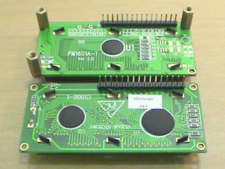
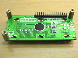
CAUTION: The controller chip that is visible on the back of the LCD display can be damaged with the static energy. Make sure to ground yourself every time you hold it, and handle it by the edges and not the PINs.
 |
 |
|
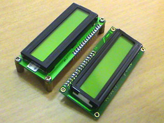
16 x 1 & 16 x 2 LCD modules with backlight (front) |
both LCDs can be used interchangeably |
 |
 |
|
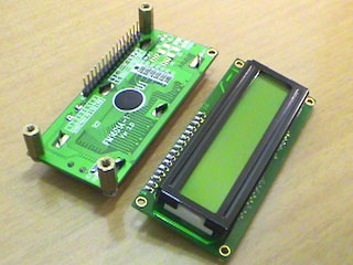
LCD modules (back) |
16 x 1 LCD with pcb standoffs and header pins |
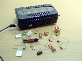
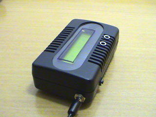
LC Meter's Enclosure (4" x 2.5" x 1")
 |
 |
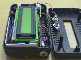
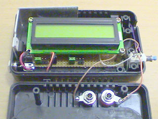
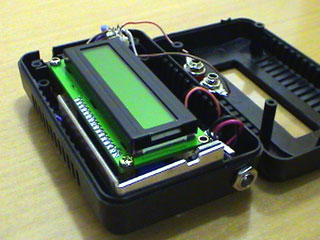
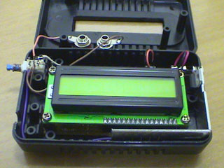
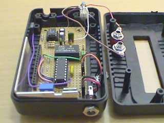
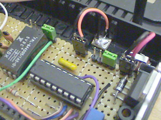
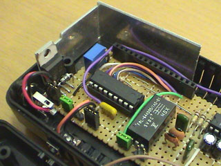
LC Meter's Construction
 |
 |
 |
 |
 |
 |
 |
 |
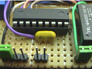 |
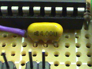 |
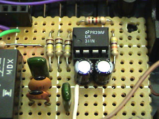 |
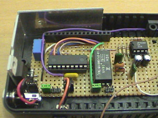 |
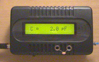
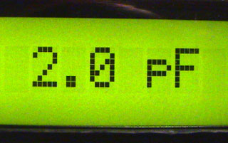
Measuring 2 pF Capacitor
 |
 |
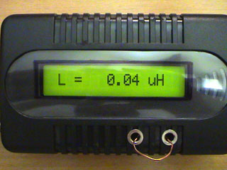
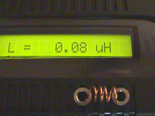
Measuring Inductance
 |
 |
|
40 nH - small piece of magnet wire |
80 nH - 4 turns of magnet wire |
 |
 |
|
90 nH coil used in FM transmitter |
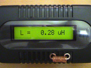
280 nH - 10 turns of magnet wire |
 |
 |
|
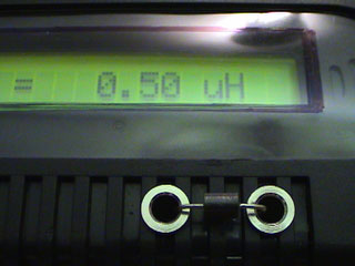
500 nH wire through choke |
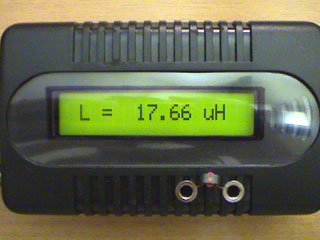
1 uH VK choke |
 |
 |
|
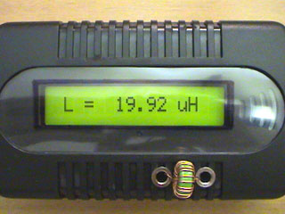
small RF toroid, 5 turns |
medium toroid |
 |
 |
|
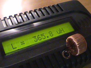
365 uH |
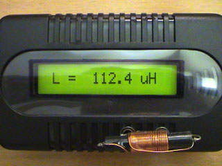
100 uH choke |
 |
 |
|
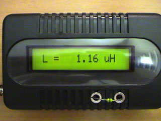
1 uH inductor |
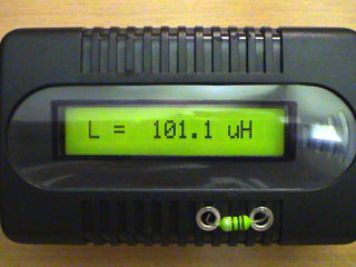
100 uH inductor |
 |
 |
|
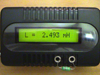
2.2 mH inductor |
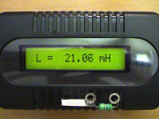
18 mH inductor |
Final Recommendations
1nF Ccal is used as a calibration capacitor so make sure that you use a good quality mylar capacitor. Keep the cables between LM311 and the terminals as short as possible to keep the stray capacitance to minimum and ensure the highest accuracy. Also, you have to use a "5V reed relay" because the current passed from PIC16F84A is very small. Reed relays require very minimal amount of current to be switched. I also suggest that you use a 7805 IC to protect the LC Meter, in case you accidentally apply a higher voltage. PIC16F84A will be damaged if you apply voltage higher than 5.5 V.
Before PIC16F84A microcontroller can be used it needs to be flashed with the following HEX program LC_METER.HEX .
