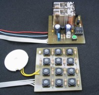
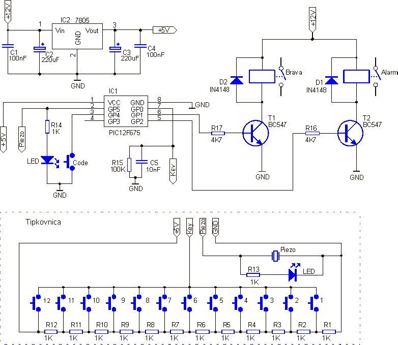
Press four keys in specific order, and relay will turn on for about to 5 seconds and that is it. But first you must memorize your code following this way: press and hold button (button on pin 3), so long until Led goes ON. Now, when Led is ON, you must type your secret code. When you do that, your code is memorized in eeprom of PIC12F675, and you can only turn ON relay using this code. If you type false code 10 times, you will turn ON “alarm” relay. It is simple for everyone.
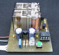
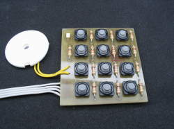
As you can see keyboard is made from a series of resistors and keys. On keyboard are connected only 3 wires, +5V, minus and a line that goes to pin 7 of microcontroller. Resistors are connected in series and on every junction there is a different value of voltage. When we press any key on keyboard, we produce a specific voltage from the specific key on pin 7 of microcontrollers.
Pin 7 on PIC12F675 is defined as input and it is internally connected to an A/D converter module. PIC12F675 has a 10 bit A/D converter and possible values of conversion range from 0-1023. So, if we have 12 keys, range between them is 85. Following that calculation "key 0" ranges from 0-85, "key1" from 86-170, "key2" from 171-256 ...
I think that is possible to connect more then 12 keys on that way with good authentication of each key.
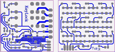
PCB and Hex file
|
PCB back side
|
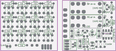 PCB components side
|
Keylock sch & pcb - pcb files in Protelu-99 SE format
Keylock.pdf - pcb in acrobat PDF format
Keylock program in hex: Keylock hex
