I am 13 I have always wanted to build a cnc machine but because inexpensive parts are hard to find in Canada I have had trouble trying to build a decent cnc controller. The purpose if this Instructable is to show that anyone can build a cnc controller using an old scanner. The scanner I used was an old OpticPro scanner. I had previously extracted the stepper motor and experimented with it but not considered it for a cnc controller. All of the controllers on the Internet had a large number of expensive transistors or were ridiculously complex. I finally stumbled across this controller and realized I could build it. By reusing the parts from the old scanner and making the case from recycled cardboard, I am cutting back on my impact on the planet. Also, because this controller is so simple, it only needs one power suply, so, it only needs 1 12 Volt (for both the logic and the motors), instead of 1 5 Volt (for the logic) and 1 12 Volt (for the motors). This saves energy, especially when you run it for a long period of time.
If you don't already know what a cnc machine is, it is a machine that uses special motors called stepper motors to moce an object a percise distance. The difference between a stepper motor and a regular DC motor, is that stepper motors "Step", not spin. if you don't understand, refer to this artical. There are two types of stepper motors. There is Bipolar, and Unipolar. Bipolar motors have 4 wires. Unipolar motors can have 5, 6 and 8 wires. The difference between these two types of motors is that unipolar motors have 4 coil inside that, when energized in a certain order, allow it to step forward and backwards. This makes them easy to control and is why we are going to use them in this instructable. Bipolar motors only have two coils that can be energized in forward, or reverse. To drive a bipolar motor you need two H-bridges. Because of this, bipolar motors motor controllers are much more complex.

Step 1
Required Parts
The parts that are required for this project are:
In the scanner:
- 1 stepper motor
- 1 ULN2003 chip
- 2 steel rods
For the enclosure:
- 1 cardboard box
The tools:
- Hot glue gun and glue
- Wire cutters/strippers
- Scissors
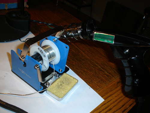
- Soldering tools
- Paint
For the controller
- 1 DB25 port (recycled from previous project)
- some wire
- 1 dc barrel jack (recycled from old RC car)
For the test rig
- 1 threaded rod
- 1 nut to match your threaded rod
- various washers and screws
- scrap wood (recycled from previous building projects)
For the control computer:
- 1 old computer (I used an old laptop)
- 1 copy of TurboCNC (get it here)
step 2
Get Parts from Old Scanner
The first step to building your cnc controller is to extract your motor and control board. I did not take any pictures of this step because every scanner is different, but it is usually as simple as removing the glass and taking out a few screws. The two parts you are looking for are the stepper motor and the control board, but also keep the nice metal rods so that you can use them to test you motor.
step 3
Remove Chip from Control Board
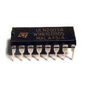
The next step is to locate the uln2003 chip on your stepper driver. If your board does not have one, you can order one online for about 50 cents. If your board has a uln2003, you must desolder the chip from the board. This step can be a bit tricky, but is not that hard. First, try to remove as much solder as you can using your desoldering pump. Once you have removed the solder, use gentle, prying force with the tip of a screwdriver. Carefully touch the tip of your iron to each pin, still applying force with your screwdriver.
step 4
Soldering
Now you need to solder the chip into your blank proto-board (I got mine at The Source).
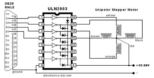
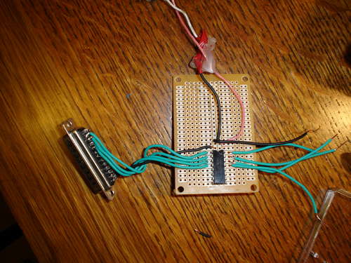
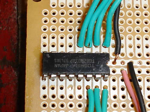
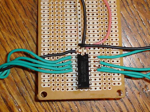
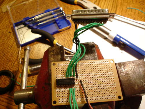
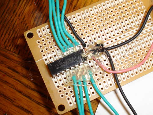
Solder each pin to the board. My board had two power rails running up the center of the board, so I soldered the positive pin on the uln2003 (see schematic from here and pictured below) to the one of the rails and the negative pin to the other rail. Then, you must solder pin 2 on your parallel port connector to pin 1 on the uln2003. Solder pin 3 on the parallel port to pin 2 on the uln2003, pin 4 on the parallel port to pin 3 on the uln2003 and pin 5 on the parallel port to pin 4 on the uln2003. Now solder pin 25 on the parallel port to the negative rail on your circuit board. Now, solder the motor to the driver. Hooking up the motor to the board requires some trial and error. I just soldered wires so that I could use alligator clips. You could also use screw terminals or something similar. Simply solder a wire to pin 16, 15, 14 and 13 on the uln2003. Then solder a wire (preferably black) to the positive rail. Your driver is almost done. Finally, solder your barrel jack (I recycled mine from an old RC car) to the power rails on your circuit board. To prevent my wires from breaking off, I put hot glue over them.
step 5
Install Control Software
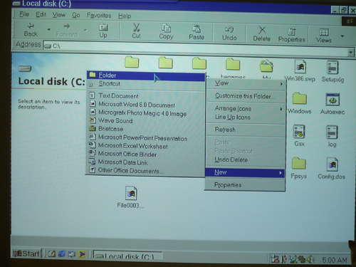
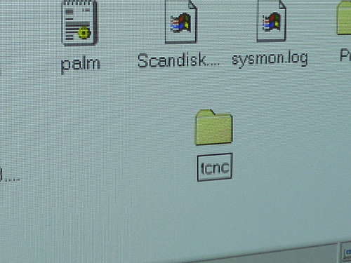
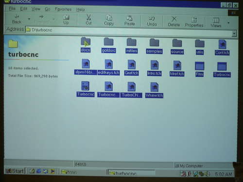
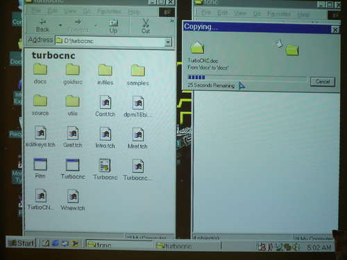
Now for the software. The only software that will work with this driver that I know of is Turbo CNC. Download it. Un-zip it and burn it to a cd. Now, on the computer that you are going to use as your controller, go to your c: // drive and make a folder called "tcnc". Next, drag the files from the CD to the folder you just made. Exit all windows. You have now installed Turbo CNC.

step 6
Configure Control Software
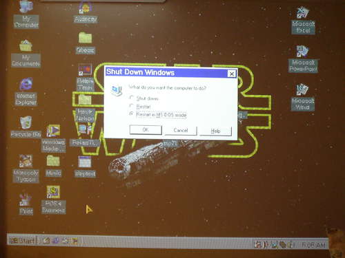
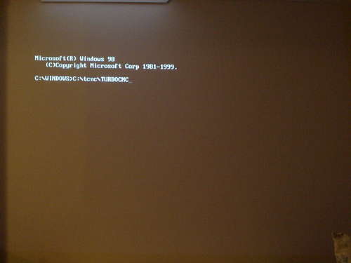
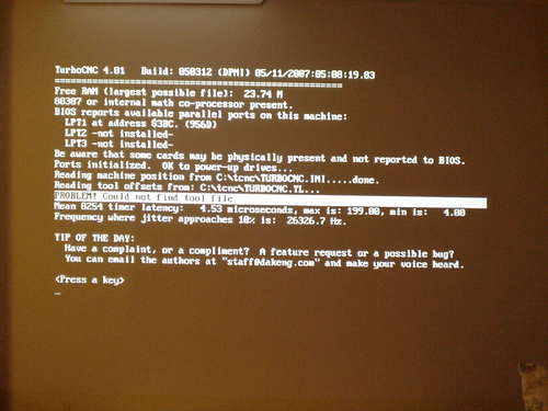
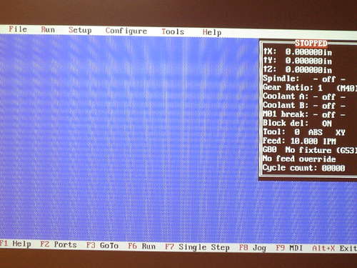
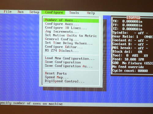
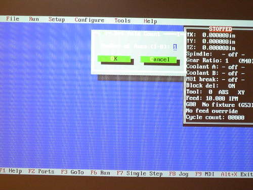
Click start and shut-down. Then check the box that says "Restart in MS-DOS mode". You will get a command prompt. At the Prompt, type "C: cncTURBOCNC". Then you will get a screen like the one in image 3. Press any key. Now you are in the main program menu. Press F1, and then use the arrow keys to select the "Configure" menu. Use the arrow keys to select "number of axis". Press Enter. Enter the number of axies you will be using. I only made one driver, so I selected "1". Press enter to continue. Now press F1 again and navigate to the "Configure" menu. Select "Configure axes", then press enter twice.
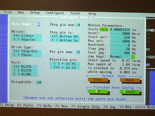
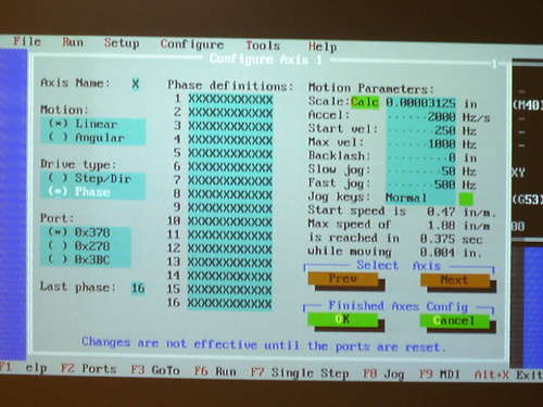
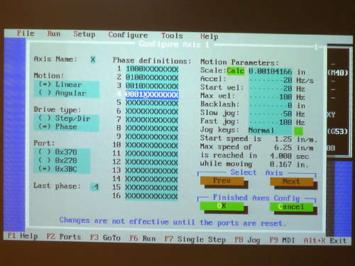
You will see a screen that looks a little confusing. Do not worry, it is not that bad. Press tab until you get the box that says"Drive Type". Press the down arrow to select 'Phase. Press tab again to select the Scale box. If your computer has a mouse in dos (mine does not), click the calc button. If yours is like mine, you can simply run the program off a computer running Windows XP or Vista by double clicking on the TURBOCNC file. Then, follow the above steps.
To use the calculator, you must find the number of steps per revolution that your motor takes. Google your motor's part number and look for how many degrees per step it takes. Then, divide 360 by the number of degrees per step to find your steps per revolution. For example, my motor turns 7.5 degrees per turn, so I divided 360 by 7.5 to get 48. Punch that number into your scale calculator. Leave the rest of the settings the same. Press ok, and then copy the number in the scale box to the scale box on the other computer. Next, change the value in the acceleration box to 20, as the default 2000 is way too fast for your system. Change the value of the start velocity box to 20, and the value of the max velocity box to 175. Change the value of the fast jog box to 175. Press tab until you get to the "Last Phase" option. Change its value to 4. Press tab until you get to the first row of x's. Copy the following into the first four boxes:
1000xxxxxxxx
0100xxxxxxxx
0010xxxxxxxx
0001xxxxxxxx
Leave the rest of the boxes as they are. Select OK. You have now set up the software.
step 7
Build a test axis
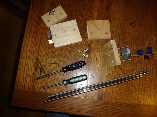
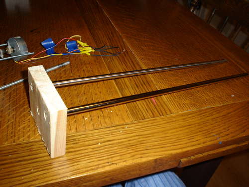
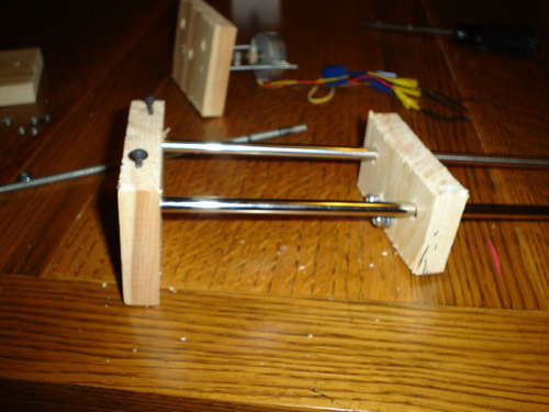
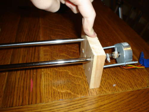
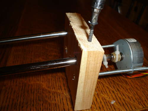
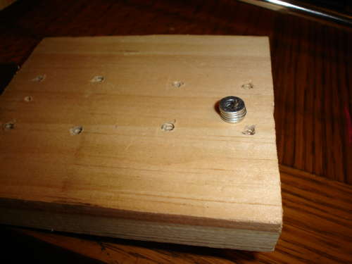
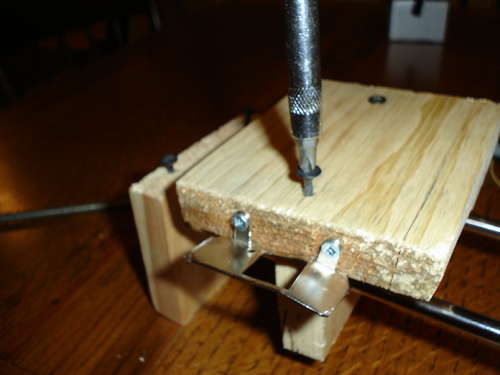
The next step is to build a simple axis to use as a test system. Cut 3 pieces of wood and clamp them together. Draw a strait line on the wood to keep your holes strait. Drill two holes on the line. Finally, drill 1 hole centered below the line. Now you can un clamp your wood.
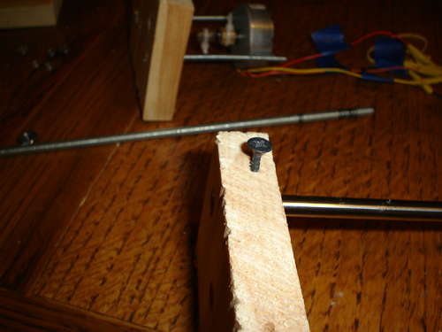
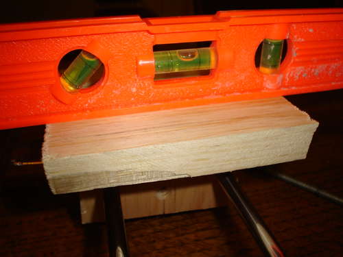
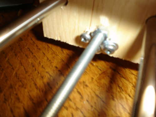
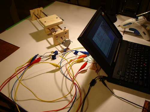
Place the two rods through the holes on the line. Screw a small screw into your rods to keep it in place. Slide your second piece of wood onto your rods. Mount your motor to the final piece of wood. It does not matter how you do this, be creative. I used two pieces of 1/8 threaded rod to hold mine in place. Now slide your wood with the motor attached to it on the other end of your rods. Screw the rods onto the wood. Slide your threaded rod through the third hole on your first piece. Screw your nut onto the rod. Slide the rod up to the second piece of wood. Turn the rod until it slides through the holes and up to the motor's shaft. Using aquarium air hose and zipties, connect the motor shaft to the threaded rod. To attach the nut to the 2nd piece of wood, I used various screws and nuts to hold my nut in place, but anything should work. Finally, cut a piece of wood the size that you want your stage to be. Screw it onto the 2nd piece of wood. Make sure that your stage is level. Mine was not, so I used washers as spacers. You have now built an axis for your motor.
step 8
Conect and Test Motor
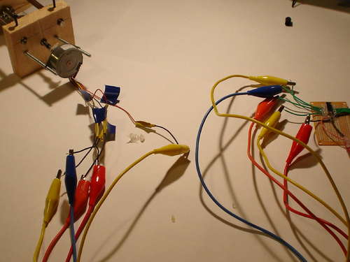
Now you need to connect the motor to the controller. First, connect the common wire (refer to your motor's datasheet) to the wire that you soldered to positive. Connecting the next four wires is a matter of trial and error. Connect them all and then change their order if your motor is taking two steps forward and one step back or something similar.
To test it, connect your 12 volt 300ma dc adapter into your barrel jack. Then, connect your DB25 port into your computer. Open the attached program in TurboCNC to test your motor wire connections. When you are done testing and changing your connection you should have a fully working axis.
To test the scale of your machine, attach a marker to your machine and run the test program. Measure the line. If yours is 1 inch long, or close to it, then your machine is good to go. If it is off, check your math. If you have made it this far, congratulations, the hardest part is done.
Make the Enclosure
Part 1
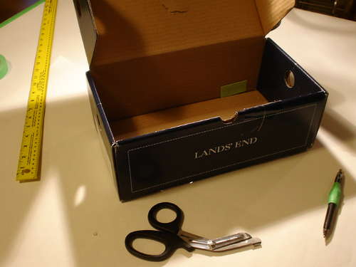
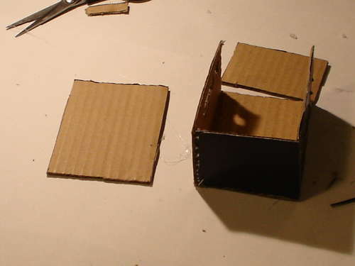
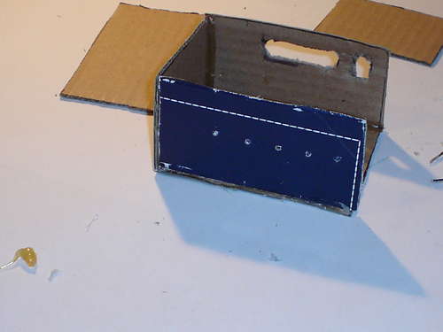
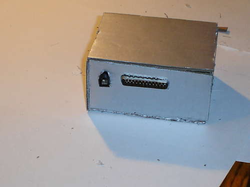
Building an enclosure is the final step. I chose to make mine out of recycled cardboard because it is better for the environment than buying a brand new plastic one. Also, since the driver is built mostly from recycled parts, it makes sense that the enclosure should be made of recycled material too. My circuit board measured about 2 inches by 3 inches, so I decide to make my enclosure 3 inches by 4 inches by 2 inches to make room for the connectors.
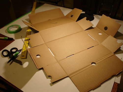
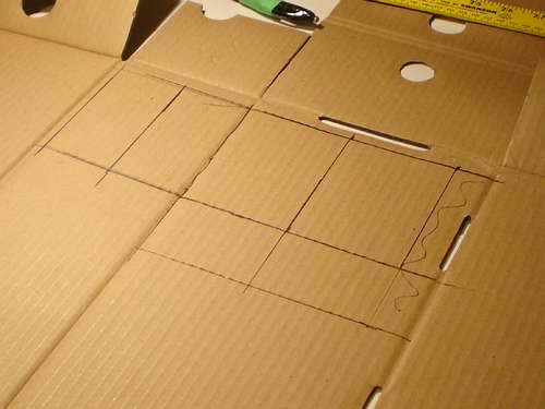
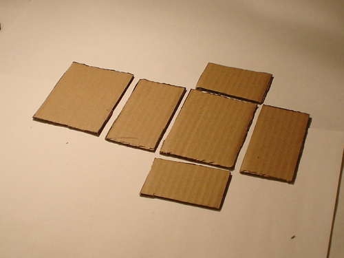
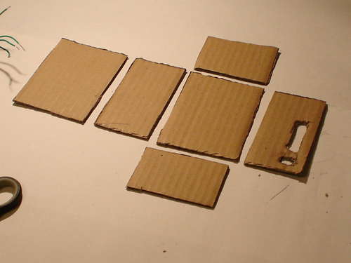
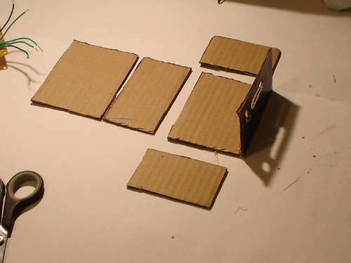
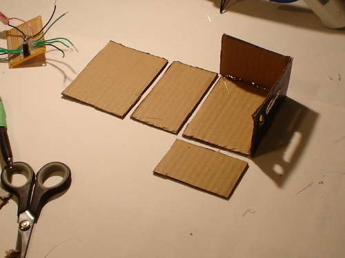
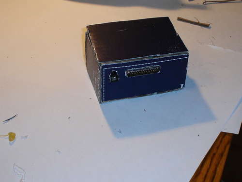
Now you need to cut your panels. Cut two rectangles that are 3 inches by 4 inches, 2 rectangles that are 2 inches by 4 inches and two panels that are 3 inches by 2 inches (see pictures). Now you need to cut the holes for the ports and plugs. Trace your parallel port plug on one of the 4x2 inch sides. Cut it out. On the same side, trace your dc barrel connector. Cut that out too.
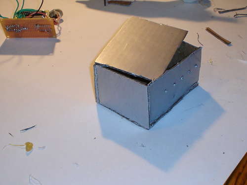
What you do in this step depends on if you soldered connectors to your motor connection wires. If you did, mount your connectors on the outside of your blank 4x2 inch panel. If you just used wires, poke 5 holes. Now, using hot glue, glue all of the panels together (except the top one, see pictures). I chose to paint mine silver.

step 10
Make the Enclousure
Part 2
Now you must glue the componants inside the enclosure. Be sure to put lots of glue on the plugs as they will be exposed to lots of force. To keep the box closed, you need to make some latches. You need to cut two tabs out of craft foam. Next, cut two strips of foam and four small squares. Glue two of the squares to each strip as shown in the photos. Glue a tab to each side of the enclosure. Glue the strips to the top of the box. This concludes building the enclosure.

step 11
Possible Uses and Conclusion
Possible uses of this controller could be:
- A cnc machine (build 3)
- Plotter (build 3)
- or anything else that requires a percise amount of movment.
This Concludes my instructable. I hope you found it interesting and helpful. Feel free to modify my design and let me know how it turned out. If you liked my instructable, please vote for it in the Epilog Laser Cutter Contest.
~Update~
Here is the three axis setup instructions and schmatic
To configure the program, follow to above steps, except when you go to enter the number of axis', enter 3. For the configuration, follow the steps above for the first axis, for the second axis, keep it the same as the above steps, except in the first four phase lines, enter the following:
"XXXX1000XXXX
XXXX0100XXXX
XXXX0010XXXX
XXXX0001XXXX"
For the last axis, follow the same steps of the other axis', only copy this into the first four phases
"XXXXXXXX1000
XXXXXXXX0100
XXXXXXXX0010
XXXXXXXX0001"

