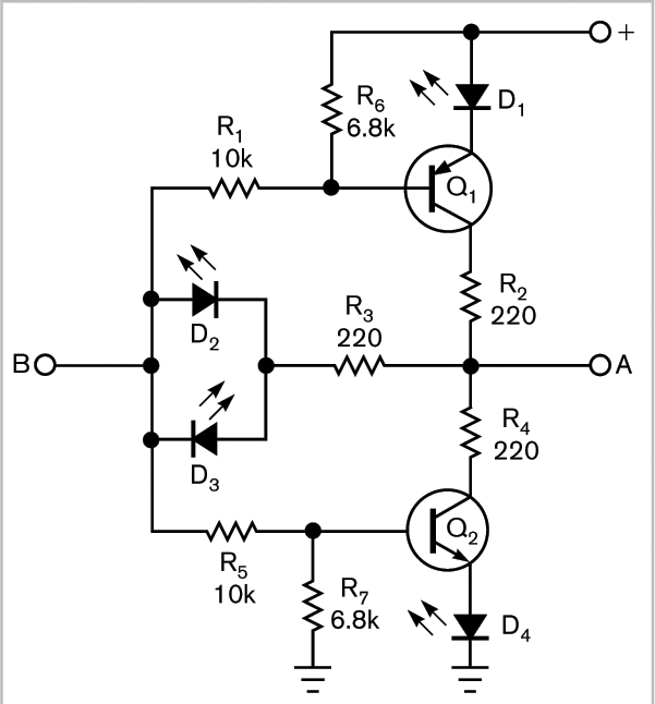
A two-line-to-four-line decoder indicates status even when both signal lines lose power.
To display the status of two digital outputs, you can simply connect an LED and its resistor on each output. You must, however, interpret, or “decode,” the displayed binary code. In addition, when no LED lights, users have no way of knowing whether it means that both outputs are off, that the power is off, or that a malfunction has occurred. In some applications, including industrial and medical settings, an indicator sending an ambiguous signal would be unacceptable. This Design Idea describes a simple circuit that resolves this problem by displaying four states on four LEDs (Figure 1). The operator need not understand binary coding, and, if no or more than one LED lights, it can mean only “no power” or “default.”

Figure 1 This simple circuit displays four states on four LEDs.
The circuit works in the following way: If both inputs A and B are low, Q1 allows current to pass through D1 and resistor R2 to A; only D1 will light. Symmetrically, if both inputs A and B are high, Q2 passes, and the current can pass from A through R4, Q2, and D4; only D4 will light. If both inputs are on different levels, only D2 or D3 will light. Table 1 shows the possibilities; all other displays point to a default, such as a bad connection, a no-power condition, or a malfunction.
Table 1 Led-lighting possibilities
|
IN |
LED |
||||
|
A |
B |
1 |
2 |
3 |
4 |
|
0 |
0 |
1 |
0 |
0 |
0 |
|
0 |
1 |
0 |
1 |
0 |
0 |
|
1 |
0 |
0 |
0 |
1 |
0 |
|
1 |
1 |
0 |
0 |
0 |
1 |
A totem-pole output that can sink and source the current for one LED must drive the A and B inputs. Resistors R2, R3, and R4 are for applying a 12-mA LED current if the power supply is 5V. No component is critical. For example, you can use generic transistors, such as the NPN 2N3904 and the PNP 2N3906. You can even use transistors with integrated base resistors, further reducing the component count.
