Sometimes, you need to remotely turn on or off a two-state system, such as a light, from multiple points. You could connect simple pushbutton switches in parallel to a single-line bus. However, if the bus simply controls a toggle flip-flop, the system must know its current state to positively ensure the new, desired state. For example, if you want to make sure the light is on, you must have visual or electrical feedback via a second line before deciding whether to toggle the flip-flop. Also, bounce-free pushbutton switches are necessary.
The circuit in Figure 1 achieves positive state control according to the length of time you activate any pushbutton switch from S1 to SN. An activation of a few milliseconds, for example, guarantees that the system is set to one state. An activation of 1 sec, for example, guarantees that the system is set to the other state. No visual or electronic feedback is necessary.
 |
||
| Figure 1. | A short activation of any one of the pushbutton switches, S1 to SN, locks the output state to Q1 high and Q2 low. A long activation sets the circuit to the opposite state: Q1 low and Q2 high. |
|
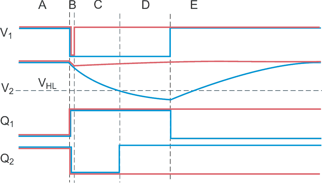
The circuit is a NAND R/S latch comprising two simple CMOS Schmitt trigger NAND gates. You can use half of a CD4093 or a 74HC132. Figure 2 depicts the signal on the circuit's individual nodes. The red lines correspond to a pushbutton's "short" activation; the blue lines correspond to a "long" activation.
 |
||
| Figure 2. | The red line corresponds to a short-activation time in section B; the blue line corresponds to a long activation time. |
|
In Figure 2, in time section A, all pushbutton switches are off, both V1 and V2 are high, and the Q1 and Q2 outputs are holding the last entered state. The figure shows this arbitrarily as Q1 low and Q2 high, but the reverse state could also be true. When one of the switches closes (section B), V1 goes low, but the delaying action of R2 and C2 keeps V2 high. This action turns Q1 high and Q2 low, regardless of the previous state in section A.
If you push the button for a short time (red line in section C), V1 returns high before V2 can approach gate IC1B's high-to-low hysteresis threshold, VHL. The circuit remains locked with Q1 high and Q2 low (red lines in sections C to E). If you push the button for a long time, V1 stays low keeping Q1 high (blue lines in sections C and D). C2 gradually discharges through R2 (section C) until V2 crosses IC1B's low-hysteresis threshold, VHL, at the end of section C. As a result, Q2 goes high. While the push button is still depressed (section D), C2 discharges even more, keeping Q2 high. When you release the pushbutton (section E), V1 returns high. Now, because Q2 is also high, Q1 goes low. C2 charges up again via R2, preparing the circuit for the next activation.
Thus, a short pushbutton activation locks Q1 high and locks Q2 low. A long activation locks Q1 low and Q2 high but only after you release the pushbutton. It is important that contact bounce or reflections from the nonterminated bus line do not influence Q1 and Q2's final state.
Because the flip-flop's loop delay is negligible, the time required to completely discharge C1 and the bus line's stray capacitance via the bus line's series resistance determine the minimum pushbutton-activation time. This time never exceeds 1 msec. The maximum short-activation time is the time over which C2 discharges to 90% of VDD, which still keeps V2 safely above VHL. For the values of R2 and C2 in Figure 1, this time is 110 msec. The minimum long-activation time is the time necessary to discharge below VHL. For a worst case of VHL=VDD/2 and for the given values of R2 and C2, this minimum time is 690 msec. There is no maximum activation time. Thus, a wide tolerance exists for both the short and the long activation times, and a large margin exists between the two.
C1 bypasses any noise that the bus may pick up from its environment. You choose the value of R1 to keep the bus line high in spite of leakage. R1 also needs to recharge C1 and the bus-line capacitance to VDD within a few milliseconds after you release the pushbutton. Thus, the values of R1 and C1 depend on the particulars of the bus.