Pulse width modulation (PWM) is a useful control technique for such applications as light dimming and motor speed control. The aim of this project was to design a low cost PWM controller that would be useful in many areas where PWM is employed. The project design centred around a single-chip solution approach, and was made possible by the powerful Atmel ATMega32 microcontroller. The peripherals on this chip are well suited to a multi-channel PWM controller with an RS232 serial interface, with enough spare I/O pins to allow an alphanumeric LCD interface, 12 button keypad support, and four analog inputs. By allowing combinations of these resources, a versatile PWM controller has been constructed.
_eng_small.jpg)
Key Design Criteria
Being designed to be a PWM controller of universal application, the first design criteria was that all PWM outputs be of equal resolution, with as many PWM outputs as possible. To this end, all three timers in the ATMega32 were set to 8-bit PWM output, resulting in a total of four PWM channels of equal resolution.
The second design criteria was that the PWM outputs be of high enough frequency that their use in motor speed control applications not cause unwanted audible effects. To prevent this, the ‘Fast PWM’ mode of timer operation within the ATMega32 was chosen, with no clock prescaling, and a clock frequency of 8MHz. This results in a final PWM frequency of 31.25kHz, well above human hearing.
The third design criteria related to user control of the PWM outputs; it was desired to have a great deal of flexibility in this regard, so that the design would suit many different target implementations with little to no modification. To address this criteria, the analog-to-digital converter on the ATMega32 may be used to control the PWM channels, as can an RS232 serial interface, or a 12-button keypad. User feedback of the PWM and ADC channels was chosen to be via an alphanumeric LCD module.
Lastly, should the user configure the PWM controller in a certain way, unused control features should not become immediately redundant. Therefore, the design have been made such that ADC channel status can be accessed via the serial interface, the keypad can log and send key presses serially, and the LCD may be user controlled via the RS232 interface. Unused microcontroller pins have been set as outputs that may be controlled via the serial interface as well. Also, user selected channel names help the design custom fit into any chosen application.
A pleasant outcome of choosing the ATMega32 for this application was that very few external components are required for the design, keeping costs low. In the discussion section, methods of lowering the cost of this project further are explored.
The Circuit
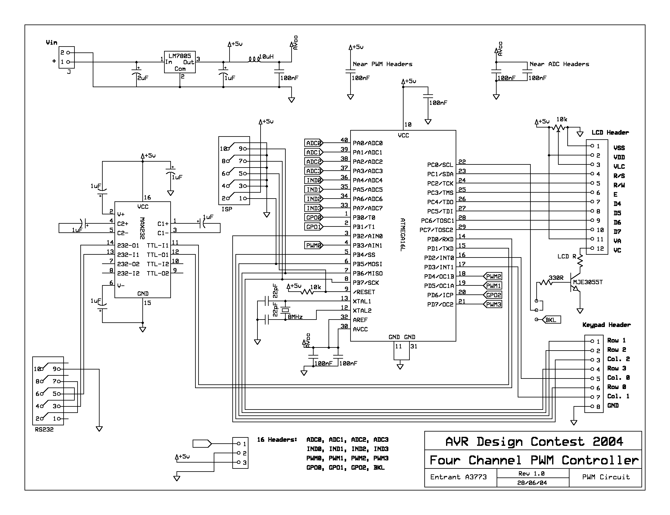
The circuit for the four channel PWM controller is very simple. An 8MHz crystal was chosen for the ATMega32 clock input, with 22pF decoupling capacitors. +5V power is regulated via an LM7805 three terminal regulator IC. A 10uH inductor and 100nF capacitor serve to remove digital switching noise from the analog voltage line. A MAX232 is used as a level converter for the RS232 interface. A standard four row, three column keypad is supported, as is any Hitachi chipset alphanumeric LCD module, though a 20x4 or 40x2 (character by line) LCD is required to view the full LCD user interface. A simple LCD backlight switching circuit is comprised of an MJE3055T power transistor, and two resistors. Three pin headers allow access to the PWM, ADC, and general purpose output lines. Finally, an ISP header was included on the board for easy software revision.
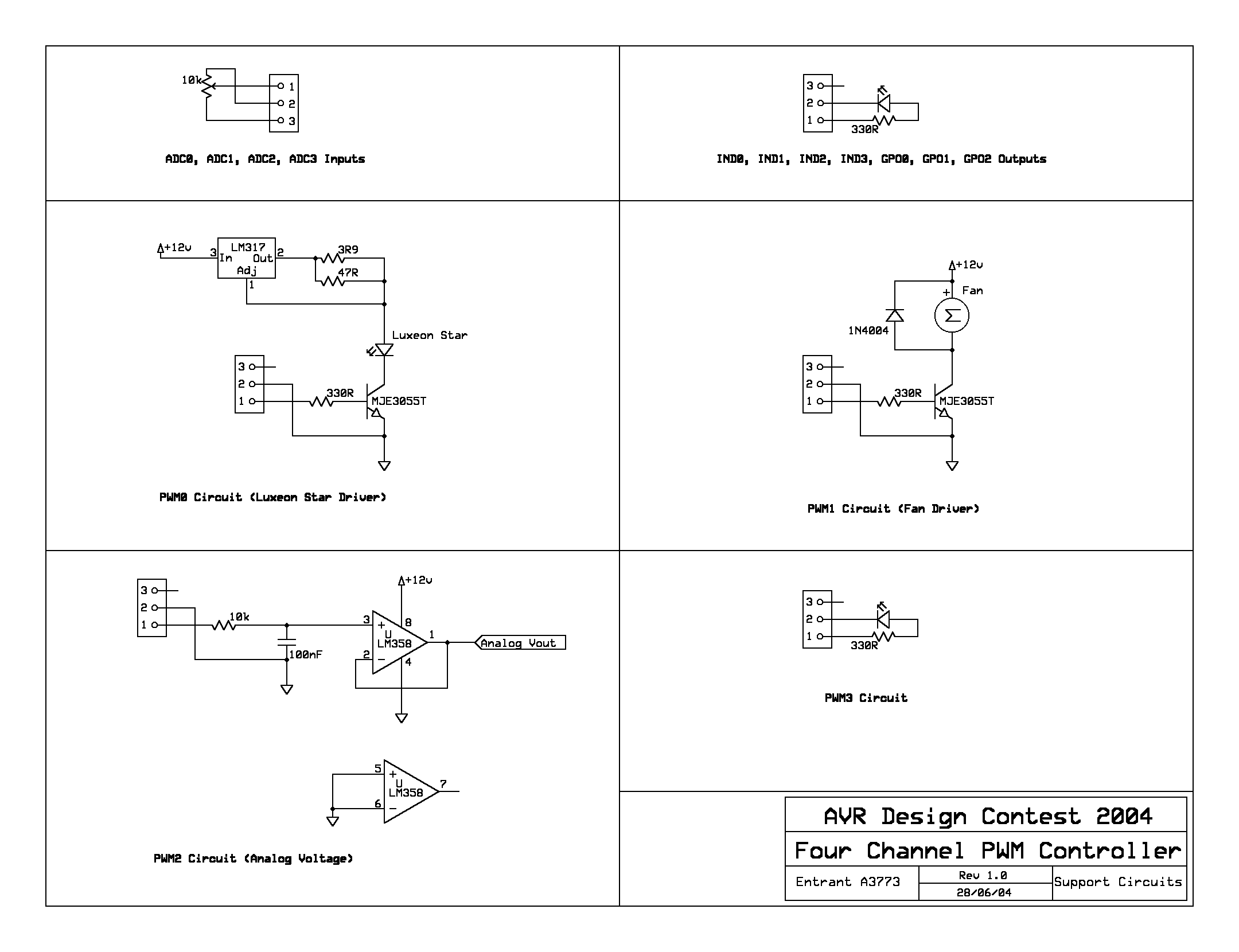
To show various uses of the PWM technique, three circuits were devised. These included a fan switching circuit (comprised of an MJE3055T transistor, resistor, and diode to control back emf from the motor), a Luxeon Star driver (again using an MJE3055T transistor as a switch for an LM317 voltage regulator set to constant current mode), and a PWM-to-analog voltage circuit (comprised of a simple RC low pass filter and an LM358 op amp creating a voltage following buffer). These circuits are not part of the PWM controller, but serve as inexpensive examples of PWM control.
Circuit Operation
Upon power-up, the PWM assumes the mode of operation last saved in its EEPROM memory. The mode of operation relates to the control type of the PWM channels (ADC control, RS232 serial control, or keypad interface control), the LCD display type (RS232 serial control, displaying PWM values, ADC values, or alternate PWM/ADC values, in either numeric or bargraph modes), and the control of the output pins (IND0, IND1, IND2, IND3, GPO0, GPO1, GPO2, and BKL, which can control the LCD backlight).
PWM pulses on all four channels are always present during circuit operation. The user may control these and other hardware features by sending control bytes via the serial interface. These control bytes are in the form of ASCII device control characters (characters 17 to 20), followed by one or more bytes to specify particular hardware and display settings. A full list of these control bytes is found in appendix XXX.
The user may also re-configure the controller via these control bytes, and save the current settings into the microcontroller’s EEPROM. The serial interface is also used by the microcontroller to send ADC values (by request) and key presses detected on the keypad (either as they occur, or sending the last 32 unsent key presses once the ‘#’ key has been pressed).
The LCD is used to display a message on start-up, and may be configured to display PWM and/or ADC channel values. The LCD also serves as a user interface for setting PWM channel values via the keypad. In this mode, pressing ‘*’ prompts the user for further input regarding channel selection and PWM settings.
The following part will be devoted the microcontroller software where mainframes of algorithm, their features will be considered.

