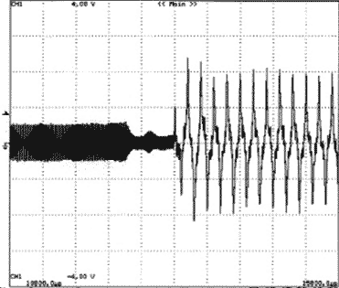
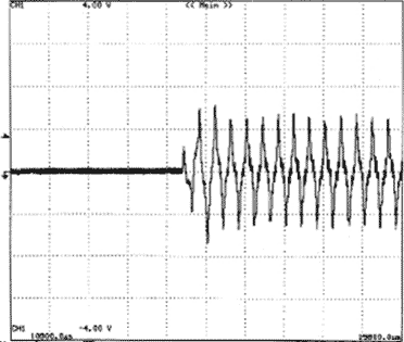
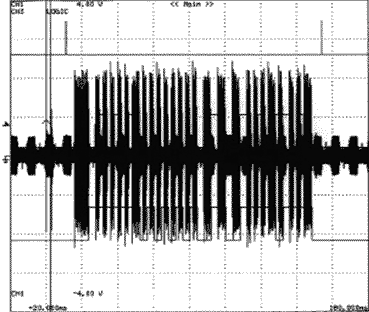
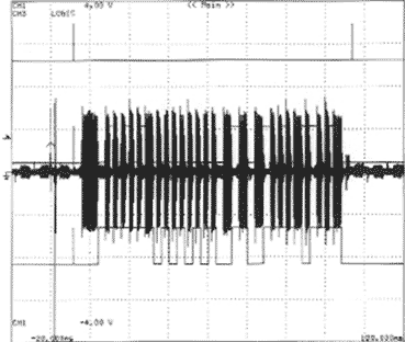
Many applications require the design of custom analog filters (Reference 1). The application for this design required simple and low-cost I/O filters for PLC (power-line communications), where low power consumption is a crucial factor. Figure 1 shows the filters, which use passive components because of the requirement for low power consumption. The PLC system needs an input and an output filter. They are 100-Hz to 20-kHz passband filters; the communication frequency is 5 kHz. The difference between the two filters lies in the input impedance. The input filter must present a 2.2-kΩ impedance, and the output filter must have a 30 Ω impedance. The circuit also needs a solid-state relay, the PVT412 from International Rectifier to isolate the output filter. When the circuit is active, the relay connects the output filter to the line. A microcontroller controls the relay to implement the signal-transmission and -reception protocols. ACTIVE_TRANS, RELAY, and Tx are the microcontroller pins that control transmission, and Rx is the pin that controls reception. Figure 2 shows waveforms before (Figure 2a) and after (Figure 2b) insertion of the input filter. Figure 3 shows waveforms before (Figure 3a) and after (Figure 3b) insertion of the output filter.
 |
||
| Figure 1. | A power-line-communications system needs input and output filters to eliminate interference. |
|
 |
||
 |
||
| Figure 2. | Without an input filter, a great deal of hash accompanies the input signal (a); the addition of the filter considerably cleans up the signal (b). |
|
 |
||
 |
||
| Figure 3. | Interference and noise are evident in the output signal (a); the addition of the output filter (b) markedly reduces the noise. |
|