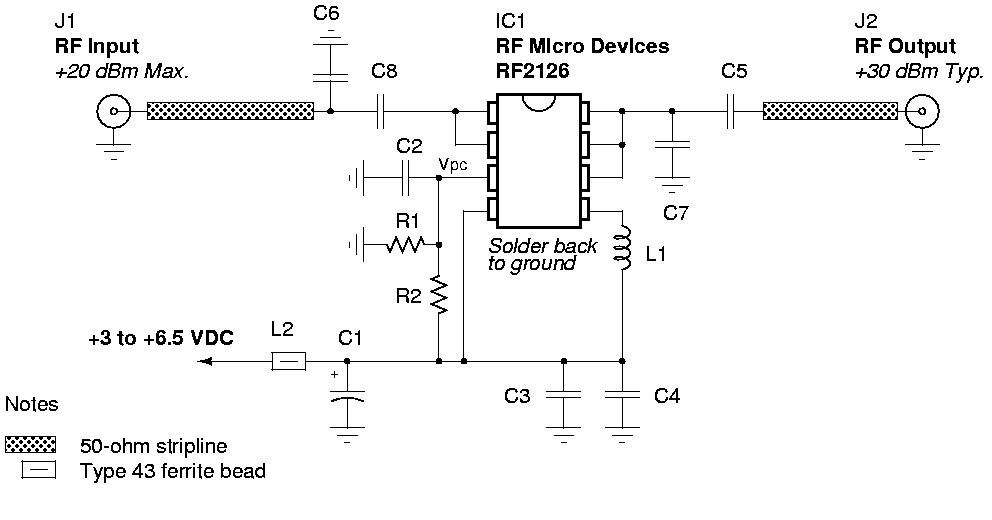
Schematic:

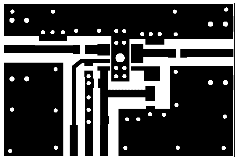
Reversed PCB pattern:

BOM:
|
|
Schematic |
Value |
Description |
Package |
|
Capacitors |
C1 |
1 µF |
electrolytic, 10%, 16V |
SMT or leaded |
|
C2, C3 |
1000 pF |
ceramic, X7R, 50V |
0603 SMT |
|
|
C4 |
22 pF |
Johanson ceramic 5%, 100V |
0504 SMT |
|
|
C5 |
3.3 pF |
ceramic, ±0.25 pF, 50V NP0 |
0402 SMT |
|
|
C6 |
2 pF |
ceramic, ±0.25 pF, 50V NP0 |
0402 SMT |
|
|
C7 |
1.8 pF |
ceramic, ±0.25 pF, 50V NP0 |
0402 SMT |
|
|
C8 |
1.6 pF |
ceramic, ±0.25 pF, 50V NP0 |
0402 SMT |
|
|
Inductors |
L1 |
4.7 nH |
2% |
0603 SMT |
|
L2 |
31 ohm @ 100 MHz |
ferrite bead, IDC 500 mA |
1206 SMT |
|
|
Resistors |
R1 |
2200 ohm |
film, 5% |
0603 SMT |
|
R2 |
1000 ohm |
film, 5% |
0603 SMT |
|
|
Integrated Circuits |
ICI |
RF Micro Devices 1 Watt 2.4 GHz power amplifier |
SOP-8 |
|
|
Other |
J1, J2 |
PCB mount SMA jacks |
Notes:
Part numbers are for reference only. Alternate components may be substituted.
It's also possible to run the RF2126 at around 6.5 volts for slightly more power output. You could try a 7805 voltage regulator with two silicon diodes (or a red LED) in series with the ground lead (cathode to ground).
Be sure to isolate the ground tab on the 7805 though or it won't work. You can even just use a plain old 7806 voltage regulator for 6 volts output.
