The classic implementation of a voltage-halving circuit uses two equal-value resistors. Using 1% resistors provides a divider output with 2% accuracy. For most applications, this performance is cost-effective and more than adequate. However, when you need extreme precision, this approach requires correspondingly accurate resistors and can become expensive. Putting feedback around a finite-gain instrumentation amplifier yields a divide-by-2 circuit with the added benefit of a buffered output (Figure 1).
 |
|
| Figure 1. | An instrumentation amplifier makes a simple divide-by-2 circuit. |
The operation of the circuit is straightforward. The instrumentation amplifier has unity gain, so the voltage it sees across its inputs appears between VREF and VOUT:
VOUT – VREF = VIN(+) – VIN(–).
But, considering the circuit in Figure 1, note that VOUT = VIN(–), and VREF = 0. Substituting in the first equation, you obtain
VOUT = VIN(+) – VOUT,
2VOUT = VIN(+),
or
VOUT =1/2 VIN(+).
Thus, you have a divide-by-2 circuit. One of the interesting features of this approach is that the input and the output offsets of the instrumentation amplifier are divided by 2 as well.
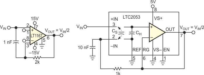
You can implement the circuit on the bench using the LT1167 or the LTC2053 instrumentation amplifiers (Figure 2). Although benchtests are unnecessary, you can introduce an RC network into the feedback path for noise shaping and to guarantee dominant-pole behavior. To test for LT1167 offset, set VIN(+) to 0 V and alternate VIN(–) between 0 V and VOUT. This test confirms that the feedback halves the total offset voltage. Dividing 10 V to 5 V, the LT1167 shows an error of 100 µV. With the more precise LTC2053, the output error in dividing 2.5 V to 1.25 V is an almost-immeasurable 2.5 µV. Using cold spray and a heat gun, you can degrade this error to 15 µV. However, perhaps equally important are the calculated worst-case results.
Worst-case calculations for the LT1167 show a maximum 1.12-mV error over 0 to 70 °C with 10 V input and 5 V output. This figure constitutes a total error of 224 ppm over temperature. Resistors that guarantee this accuracy would need a maximum tolerance of 112 ppm each over temperature. The error budget of a resistor-divider solution would require an initial ratio match of approximately 50 ppm with a temperature-coefficient match better than 1 ppm/°C.
 |
|
| Figure 2. | Practical implementations of the circuit in Figure 1 use the LT1167 (a) and the LTC2053 (b). |
Worst-case calculations for the LTC2053 with 2.5 V input and 1.25 V output show a maximum 80-µV error over 0 to 70 °C. This figure constitutes a total error of 64 ppm over temperature. Resistors that guarantee this accuracy would need a maximum tolerance of 32 ppm each over temperature. The error budget of a resistor-divider solution would require an initial ratio match of approximately 15 ppm (0.0015%) with a temperature-coefficient match better than 0.25 ppm/°C. In either case, resistors of this caliber would be extraordinarily expensive if available at all. Also, the amplifiers provide the additional benefits of high input impedance and output buffering. Moreover, the error calculations include the effects of input offset voltage, bias current, gain error, and common-mode rejection ratio, which a resistor op amp would still have to add.