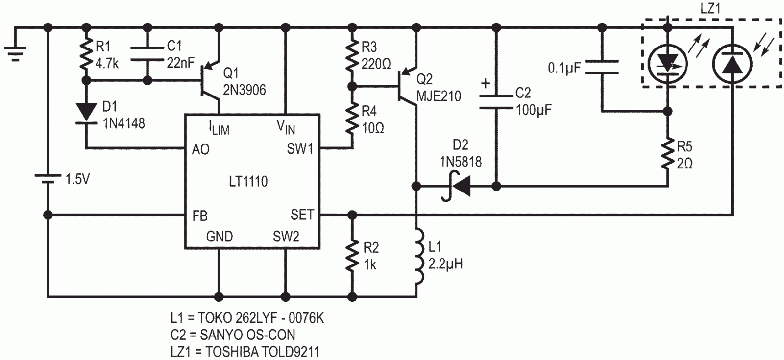
Recently available visible lasers can be operated from 1.5 V supplies, given appropriate drive circuits. Because these lasers are exceptionally sensitive to overdrive, power to the laser must be carefully controlled lest it be damaged. Over-currents as brief as 2 microseconds can cause damage.
In the circuit of Figure 1, an LT1110 switching regulator serves as the controller within the single cell powered laser diode driver. The LT1110 regulator is a high speed LT1073.
The LT1110 is used here as an FM controller, driving a PNP power switch Q2, with a typical “ON” time of 1.5 microseconds. Current in L1 reaches a peak value of about 1.0 A. The output capacitor C2 has been specified for low ESR, and should not be substituted (damage to the laser diode may result).
 |
|
| Figure 1. | LT1110 Laser diode driver operating from a single cell. |
The Gain Block output of the LT1110 functions with Q1 as an error amplifier. The differential inputs compare the photodiode current developed as a voltage across R2 to the 212 mV reference. The amplifier drives Q1, which modulates current into the ILIM pin. This varies oscillator frequency to control average current.
Overall frequency compensation is provided by R1 and C1, values carefully chosen to eliminate power-up overshoot. The value of current sense resistor R2 determines the laser diode power, as shown the 1000 ohms results in about a 0.8 milliwatt output.
