In a three-phase ac system, a power source with three wires delivers ac potentials of equal frequency and amplitudes with respect to a zero-potential wire, each shifted in phase by 120° from one wire to the next. Two possibilities exist for establishing a phase sequence. In the first, voltage on the second wire shifts by 120° relative to the first, and, in the second, a –120° shift occurs with respect to the first wire. Phase order determines the direction of rotation of three-phase ac motors and affects other equipment that requires the correct phase sequence: a positive 120° shift. You can use a few low-cost passive components to build a phase-sequence indicator.
 |
|
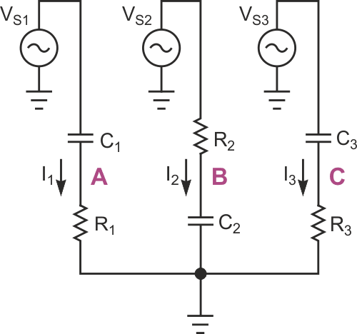
| Figure 1. | This conceptual circuit can detect both phase sequences. |
Figure 1 shows a conceptual circuit that can detect both phase sequences. For certain component values, the following conditions apply: The voltages across R1 and C2 are equal – that is, their magnitudes and phases are the same – only when VS2 occurs exactly 120° ahead of VS1, which indicates the correct phase sequence. In this case, the voltage between points A and B is zero. Conversely, the voltages across C2 and R3 are equal only when VS2 is ahead of VS3 by 120°, which corresponds to a reversed sequence.
 |
|
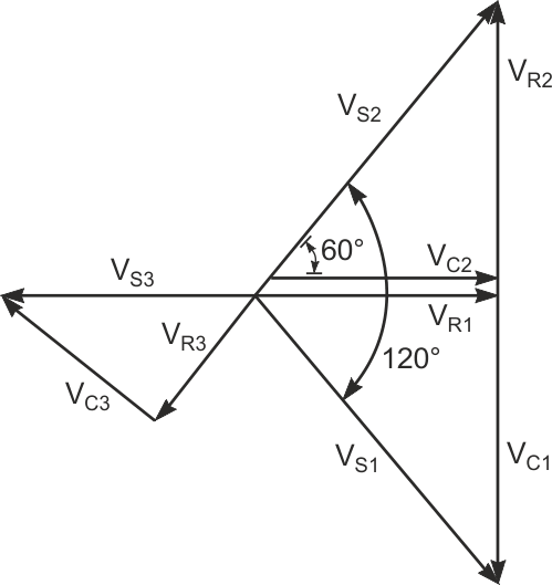
| Figure 2. | When the voltages across R1 and C2 are equal, VC1 = –VR2, VC1 + VR1 = VS1, and VC2 + VR2 = VS2. |
Referring to the phasor diagram in Figure 2, when the voltages across R1 and C2 are equal,

and

The following equations satisfy these conditions:

and

You calculate the component values by solving the following equations:

and

where
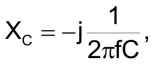
and f represents the frequency of the VS voltages.
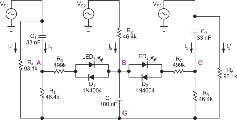
Also, to ensure detection of a reversed phase sequence, C1 = C3, and R1 = R3; that is, the components in the third branch are identical to those in the first branch. The phase-sequence-detection circuit in Figure 3 eliminates the requirement for an accessible ground wire by adding resistors R4 and R5 that connect in parallel with the first and third branches. Eliminating the ground-wire requirement also dictates a ratio between |XC1 + R1 | and |XC2 + R2 |. For no current to flow to ground from Node G, the sum of currents in the branches must equal zero, and, if you disconnect Node G from ground, its potential with respect to ground is also zero.
 |
|
| Figure 3. | This phase-indicator circuit balances branch voltages and currents and requires no ground reference. These component values are for a 60-Hz line frequency. |
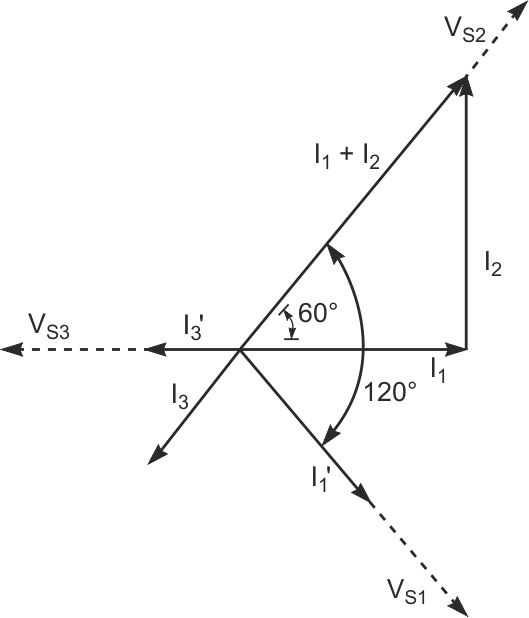
As long as the proportions of XC1 to R1, XC2 to R2, and XC3 to R3 remain as noted, the balance of voltage drops remains across R1, C2, and R3. Multiplying the impedance of any branch by a constant influences only the magnitude of the currents through the respective branch. The current through any branch presents the same phase angle as the voltage across a resistor in the branch. The phasor diagram in Figure 4 shows the currents in Figure 3. From this diagram, if

then

Thus, I3 has half the magnitude of and an exactly opposite direction from (I1 + I2).
 |
|
| Figure 4. | I3 has half the magnitude and an exactly opposite direction to (I1+ I2) in Figure 3. |
A vector diagram of the currents shows that adding two currents, each with magnitudes equal to I3 and the same phases as VS1 and VS3, produces a summed current with the same magnitude and phase as I3; therefore, the total current at Node G is zero:

To make the sum of the currents equal zero,

The two LEDs in Figure 3 indicate correct or reversed-phase sequence. When LED2 lights and LED1 remains dark, the voltage between nodes A and B is 0 V, which corresponds to a correct phase sequence. A reversed-phase sequence lights LED1 while LED2 remains dark. The diodes connected in parallel with the LEDs protect against exceeding the LEDs' reverse-breakdown voltages, and resistors R6 and R7 limit forward currents through the LEDs. For greater sensitivity, you can replace the LEDs with high-input-impedance ac-detector circuits.
The circuit's final version includes indicators that show whether all three phases carry voltage. In the circuit in Figure 3, a phase that carries 0 V lights both LEDs. Depending on your application, you can connect voltage-detection circuits comprising LEDs and protection diodes in series with current-limiting resistors between VS1, VS2, and VS3 and Node G. You can also use low-wattage neon lamps with appropriate series-current-limiting resistors.
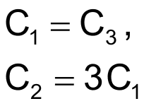
When selecting components, ensure that their values conform to the following proportions. For an arbitrarily chosen value for C1,

and

When you select a value for C1, the currents through the detection circuitry should be significantly lower than the currents through the branches, which excludes arbitrarily low values for C1.
