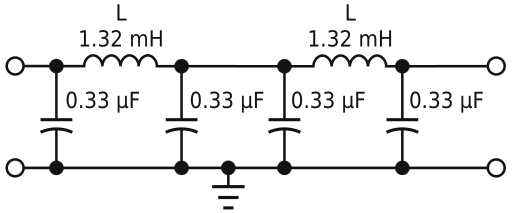
Low-frequency filters, particularly at audio frequencies, usually take the form of active filters. These filters eliminate expensive inductors with windings of many turns. Both analog and digital active filters are most compatible with large-scale integration at the subsystem and system levels. However, passive filters remain a viable option when you quickly need low-cost prototypes and test pieces (Reference 1). These filters use no external dc excitation and require no complex pc boards. You can easily wind some filter inductors using manual techniques. Moreover, inductors can handle greater power levels than small-signal active devices. You can construct a simple lowpass filter with a 3-dB cutoff frequency of 10 kHz; a source/load impedance of 50 Ω; five poles; and 0.02-dB-ripple, Chebyshev response. Figure 1 shows the filter's schematic;
 |
| Figure 1. |
A five-pole passive lowpass filter yields sharp cutoff characteristics
and low ripple |
Table 1 provides the parts list.
| Table 1. |
Parts list for five-pole lowpass filter |
| Function |
Value |
Realization |
Quantity |
| Inductors |
1.32 mH |
28 turns No. 26 on Fair Rite toroid
No. 597700601-0.825-in. outer
diameterx0.525x0.25 in. thick |
Two |
| Capacitors |
0.33 µF |
Polypropylene with 2% tolerance |
Four |
| Connectors |
BNC female |
Four-hole panel receptacle |
Two |
| Enclosure |
Aluminum box |
Hammond 1590B/Bud CU-124 |
One |
| Board |
Cut by hand |
Vector board 169PP44C1 |
One |
| Standoffs |
Male/female |
Amatom 9794-SS-0440 |
Six |
|
Table 2 shows the measured frequency response with 50 Ω source and load impedances. The extremely low passband-insertion loss indicates that the inductors' unloaded Q is greater than 100. You could use smaller inductors, such as toroids with 0.5- or 0.625-in. diameters with acceptable insertion losses (Reference 2). Note that expensive Litz wire is unnecessary. Lowpass filters need much lower inductor unloaded Q values than do most bandpass filters. At very low frequencies, both inductors and capacitors can become large. By using moderate filter-impedance levels, such as 50 or 75 Ohm at kilohertz frequencies, inductor values can be lower than 10 mH. With high-permeability inductor cores, fewer turns are required, and hand-winding is usually feasible. However, capacitors become large for lower filter impedances. For the traditional 600 Ohm impedance used at audio frequencies, inductors are larger by an order of magnitude. If you reduce the cutoff frequency from 10 to 1 kHz, the inductor values also increase by an order of magnitude.
| Table 2. |
Measured frequency response for lowpass filter |
| Frequency (kHz) |
Insertion loss (dB) |
Frequency (kHz) |
Insertion loss (dB) |
| 1 |
0.1 |
11 |
6.5 |
| 3 |
0.1 |
13 |
15 |
| 5 |
0.1 |
15 |
22.6 |
| 7 |
0.15 |
20 |
36.5 |
| 8 |
0.25 |
30 |
Greater than 50 |
| 9 |
0.6 |
To 1 MHz |
Greater than 50 |
| 10 |
3.1 |
|
|
|
References
- Wetherhold, Ed, “Audio Filters for EN 55020 Testing,” Interference Engineers' Master, 1998.
- DeMaw, MF, Ferromagnetic Core Design and Application Handbook, Chapter 3, Prentice-Hall, 1981.
