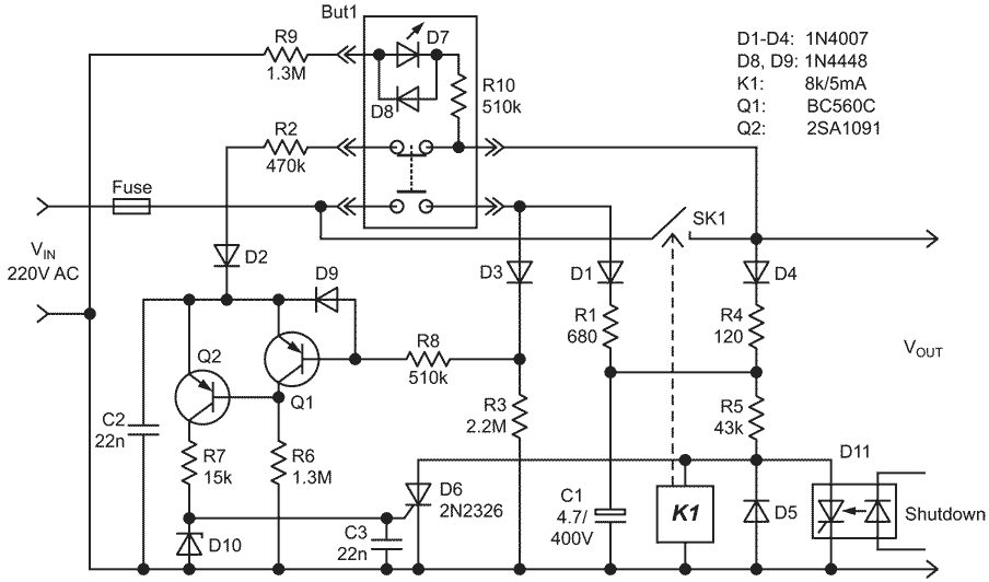
The purpose of this Design Idea was to improve reliability, add new features, and replace a latching power switch with a momentary one.
The features are:
- The switch has foolproof protection against too frequent switching, which can be harmful for many applications.
- It can handle significant power because manual control and switching are separated.
- If an unexpected power outage occurs, the switch disconnects and remains off after power returns.
- A unit can switch itself off.
Figure 1 shows one-pole load isolation when SK1 is opened, but a two-pole relay can just as easily be used.
 |
|
| Figure 1. |
The control button BUT1 requires normally open and normally closed contacts, which must not be closed simultaneously.
Initially, while the button is not pressed, the switch is opened because relay K1 is deactivated. The normally-open contacts of the relay and the button are the only components under voltage in this state.
When the button is actuated for the first time, the capacitor C1 is charged through D1 & R1, and relay K1 is activated, closing its contact pair SK1. The relay from now on is powered via D4 & R4 also.
When the button is released, the NC contacts allow C2 to charge to about one-half of the mains voltage through R2 & D2. This prepares the switch for subsequent shutdown when the button is pressed again. Q1 is on and Q2 is off.
With the next press of the button, both transistors change their state, and the discharge current of C2 triggers SCR D6, de-energizing the relay and disconnecting the load. Due to the latching action of the SCR, this state cannot be reversed by any subsequent actuation of the button while C1 is not discharged.
Releasing the button returns the circuit to its initial state.
LED D7 and protection diode D8 are embedded in the button. Modern LEDs are bright enough with a current is in range of 0.01 – 0.02 mA, so despite the relatively high voltage, the total power consumption for the illumination is about 5 – 10 mW or less.
An optional opto-thyristor D11 adds the ability for a powered system to be switched off from within the system.
Resistor R1 protects the button's contacts from an inrush current. The constant R1C1 moderates the turn-on time.
The capacitor C3 should be placed close to D6 to prevent false triggering due to EMI.
Resistors R9 & R10 limit the current through LED D7. There are two resistors for mains of 220 V (to reduce the voltage on each resistor). For mains of 110 V, R9 alone can be used.
The value of R5 depends on the resistance of the relay coil (r) and value of VIN.
Either SCR should withstand a peak current of:

and its off-state voltage should be not less than:

