“The unfortunate relationship between servo systems and oscillators is very apparent in thermal-control systems,” said Linear Technology's Jim Williams (Reference 1). Although high-performance temperature control looks simple in theory, it proves to be anything but simple in practice. Over the years, designers have devised a long laundry list of feedback techniques and control strategies to tame the dynamic-stability gremlins that inhabit temperature-control servo loops. Many of these designs integrate the temperature-control error term TS – T in an attempt to force the control-loop error to converge toward zero (Reference 2).
One tempting and “simple” alternative approach makes the heater power proportional to the integrated temperature error alone. This “straight-integration” algorithm samples the temperature, T, and subtracts it from the setpoint, TS. Then, on each cycle through the loop, the loop gain, F, multiplies the difference, TS – T, and adds it as a cumulative adjustment to the heater-power setting, H. Consequently,
H = H + F × (TS – T).
The resulting servo loop offers many desirable properties that include simplicity and zero steady-state error. Unfortunately, as Figure 1 shows, it also exhibits an undesirable property: an oscillation that never allows final convergence to TS. Persistent oscillation is all but inevitable because, by the time that the system's temperature corrects from a deviation and struggles back to T = TS, the heater power inevitably gets grossly overcorrected. In fact, the resulting overshoot of H is likely to grow as large as the original perturbation. Later in the cycle, H's opposite undershoot grows as large as the initial overshoot, and so on.
 |
|
| Figure 1. | A simple integrating control algorithm virtually guarantees that the system’s temperature oscillates and never converges to the setpoint temperature, TS. |
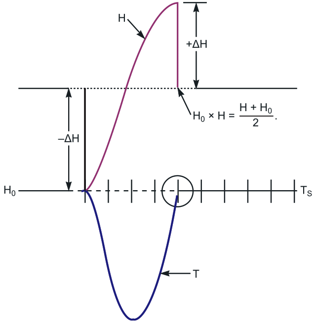
Acting on intuition, you might attempt to fix the problem by adopting a better estimate of H whenever the system's temperature crosses the setpoint, T = TS). This Design Idea outlines a TBH (take-back-half) method that takes deliberate advantage of the approximate equality of straight-integration's undamped overshoots and undershoots. To do so, you introduce variable H0 and run the modified servo loop, except for the instant when the sampled temperature, T, passes through the setpoint, T = TS. Whenever a setpoint crossing occurs, the bisecting value (H + HO)/2 replaces both H and H0. As a result, at each setpoint crossing, H and HO are midway between the values corresponding to the current (H) and previous (H0) crossings. This action takes back half of the adjustment applied to the heater setting between crossings. Figure 2 shows how a simulated TBH algorithm forces rapid half-cycle convergence.
 |
|
| Figure 2. | In this simulation, applying the “take-back-half” algorithm forces convergence to the setpoint value in a single half-cycle. |
Successful applications of the TBH algorithm range from precision temperature control of miniaturized scientific instrumentation to managing HVAC (heating/ventilation/air-conditioning) settings for crew rest areas in Boeing's 777 airliner. Experience with TBH applications shows that, with a reasonable choice for loop gain, F, the algorithm exhibits robust stability.
In general, a TBH system's natural cycle time is proportional to the square root of the ratio of the thermal time constant to F. Based on both simulations and experiments, a cycle time that's at least eight times longer than the heater-sensor time delay ensures convergence. Therefore, setting loop gain F low always achieves convergence, and the steady-state error, TS – T, remains equal to zero.
Figure 3 shows a practical example of a TBH controller that's suitable for managing large thermal loads. Thermistor RT1 senses heater temperature. The output of error-signal integrator IC5A ramps negative when TS < T and ramps positive when TS > T, producing a control signal that's applied to comparator IC5C, which in turn drives a solid-state relay, IC3, which is rated for 10 A loads.
 |
|
| Figure 3. | For safety, this version of a TBH heater controller features full isolation of the ac-line and control circuits. |
Comparator IC5D and the reverse-parallel diodes formed by the collector-base junctions of Q6 and Q7, and the CMOS switches of IC1 perform the TBH zero-crossing convergence function.
In most temperature-control circuits, it's advantageous to apply a reasonably linear feedforward term that represents the actual ac voltage applied to the heater; the need for complete galvanic isolation between the control and the power-handling circuits complicates this requirement. In this example, a linear isolation circuit comprising a PS2501-2 dual-LED/phototransistor optoisolator (IC2A and IC2B) and op-amp IC5B delivers feedback current to C15 and IC5C that's proportional to the averaged ac heater current. As a bonus, the feedback circuit provides partial instantaneous compensation for ac-line voltage fluctuations.
References
- Williams, Jim, Linear Applications Handbook, Linear Technology, 1990.
- “Hybrid Digital-Analog Proportional-Integral Temperature Controller“
