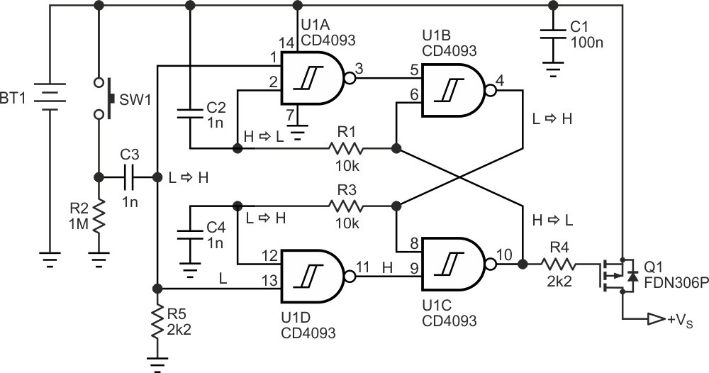
The circuit in Figure 1 shows an electronic switch driven by a momentary pushbutton, which turns the power alternately on and off. It was designed for battery-powered equipment. The easiest way to implement it is to use a flip-flop IC, such as the 4013. However, with the 4093 IC used here, the quiescent current is four times lower (0.5 µA versus 2.0 µA at 25 °C).
 |
|
| Figure 1. | Latching switch designed to save battery power. |
U1B and U1C form a latch. Thanks to the connection of C2 to the positive rail and C4 to ground, when the circuit is powered, U1B output decreases and U1C output increases, turning off Q1.
When the switch is pressed, a positive pulse appears on R5. U1D does not change state (pin 12 is low), but U1A output transmits a low pulse, which inverts the state of the latch and turns on Q1.
Because time constants R1·C2 and R3·C4 are longer than R2·C3 during the duration of the pulse, the inputs of U1A and U1D do not change; otherwise, the system will undergo a change of state continuously. When the switch pulse is well extinguished, the latches’ outputs arrive at the U1A and U1D inputs. Now it is the U1D gate that changes state with the next switch pulse, turning off Q1.
The circuit can work supplied from 3 V to 15 V.
