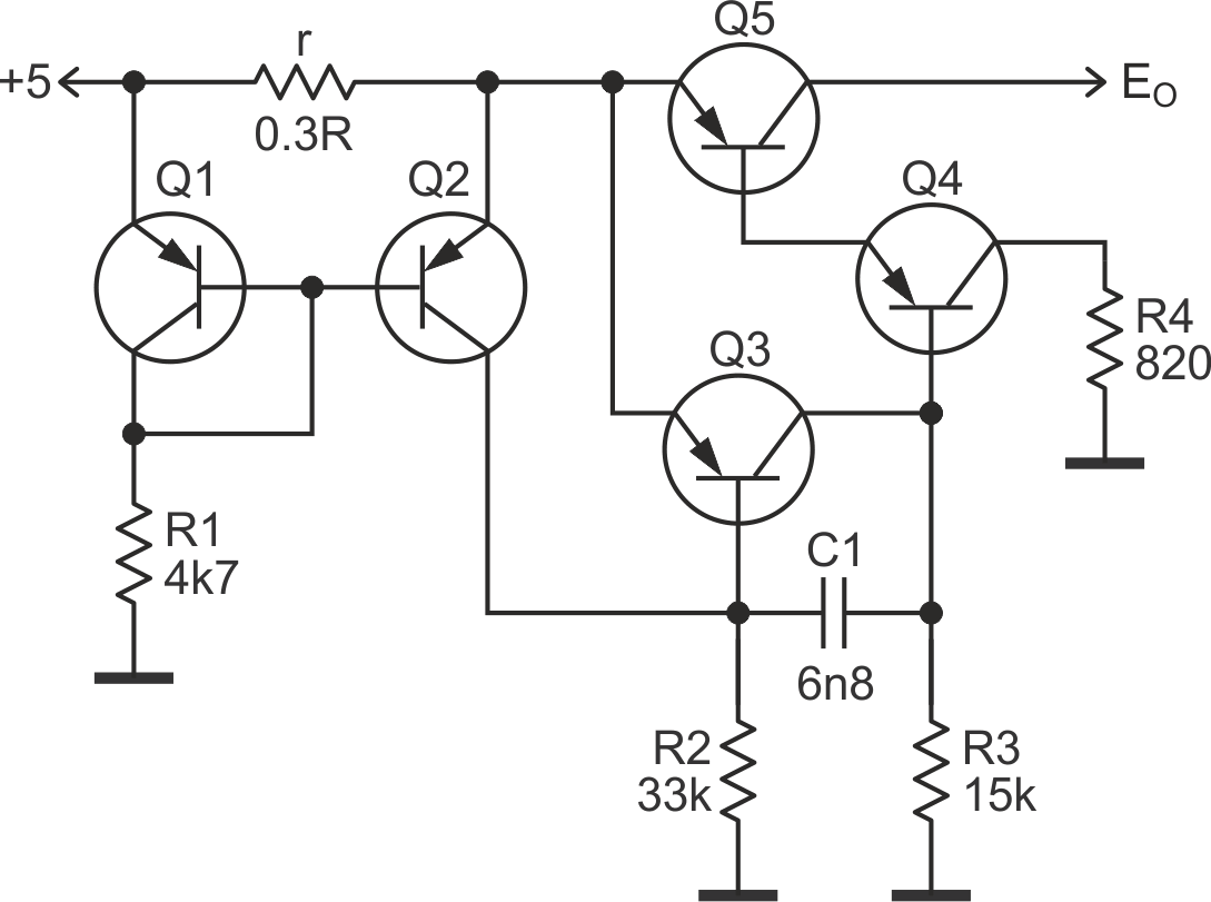
The fuse described in this design idea does not drop the connection, it simply limits the output current. A behavior that is similar to a polyfuse, however the circuit shown in Figure 1 is more accurate, does not depend on ambient temperature (polyfuses rely on temperature), and resets far more rapidly (see Reference 1).
“The device may not return to its original resistance value; it will most likely stabilize at a significantly higher resistance (up to 4 times initial value). It could take hours, days, weeks or even years for the device to return to a resistance value similar to its original value, if at all.”
 |
|
| Figure 1. | The Q1, Q2 transistor pair provide thermal compensated monitoring of the voltage drop on resistor r; when this drop rises to ~20 mV, the fuse goes “on”, limiting output current to ~150 mA. |
When the fuse is “off”, the voltage drop may be as low as 30 to 50 mV. With the value of resistor (r) as 0.13 Ω, the circuit limits output current to ~150 mA.
While this circuit is more complex than your standard resettable fuse, more costly gadgets can most certainly afford a not dirty-chip fuse. The circuit consists of 5 PNP transistors (of which 4 may already be part of a chip), 5 resistors, and 1 ceramic capacitor.
The pair Q1, Q2 provides thermal compensated monitoring of the voltage drop on resistor r; when this drop rises to about 20 mV the fuse goes “on”.
Capacitor C1 provides compensation in the loop. Transistor Q5 should dissipate all power EI × IOUT and its VCE(SAT) should be as low as possible to reduce voltage losses, it also should have a decent hFE. I used TIP32, but this was long ago, so it is possible to find much better substitutes.
