The 0- to 20-mA current loop is a reliable means of data communication in industrial applications. These circuits use a precision shunt in the receiver to convert the current signal into a voltage signal. Accidentally connecting the precision shunts to the current-loop power supply can cause damage, after which you must replace the shunt and recalibrate the system. To avoid that expense, you can use a microcontroller-controlled protection circuit (Figure 1).
 |
|
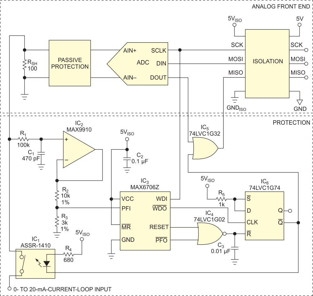
| Figure 1. | This circuit protects the isolated analog front end of a current loop. For simplicity, the drawing omits power and ground connections for IC2, IC4, IC5, and IC6. |
With conventional techniques, you protect the shunt with a fast fuse or by turning off the loop with an automatic switch, which then turns back on after a specified period. The circuit in Figure 1 provides protection that is much faster than a fuse. IC1, the slowest device in the circuit, switches off in less than 500 µsec. It offers a higher-precision switching threshold than a fuse, and, of course, there’s no fuse to replace. Rather than making you cycle power to restore the loop, the microcontroller provides control of the protection circuit. The microcontroller also logs the event, thereby providing a record that the system invoked the protection circuit.
The protection circuit has virtually no effect on the analog front end. The IC2 buffer ensures an input current of less than 30 pA. The on-resistance of IC1 is less than 2 Ω. The circuit needs no additional isolated data channels or microcontroller-I/O ports, and it prevents damage during system installation or repair. It also turns off the loop after power-up and when no power is available.
You implement the protection algorithm with a power-fail comparator and a watchdog circuit, available as separate outputs on IC3, together with IC6, a Dtype flip-flop.
At power-up, the flip-flop is in the reset state, and the current loop is open, due to a high-level reset signal from IC3 driving IC4, a NOR gate. After the first low-to-high transition on the SCK (clock-signal) line, a rising edge from IC3’s /WDO (watchdog output) sets the flip-flop and pulls current through the solid-state relay, IC1, thus connecting the input to the loop.
In the event of a loop-current overload greater than 27 mA, a high level from the PFO (power-fail-output) comparator on IC3 resets the flip-flop and switches off IC1. Thanks to the IC5 gate, the microcontroller inputs ones at the MISO (master input/slave output), meaning overcurrent.
To again switch on the loop, the micro controller must stop the SCK line for at least 2.4 sec. The next low-to-high transition on SCK then reconnects the current loop.
