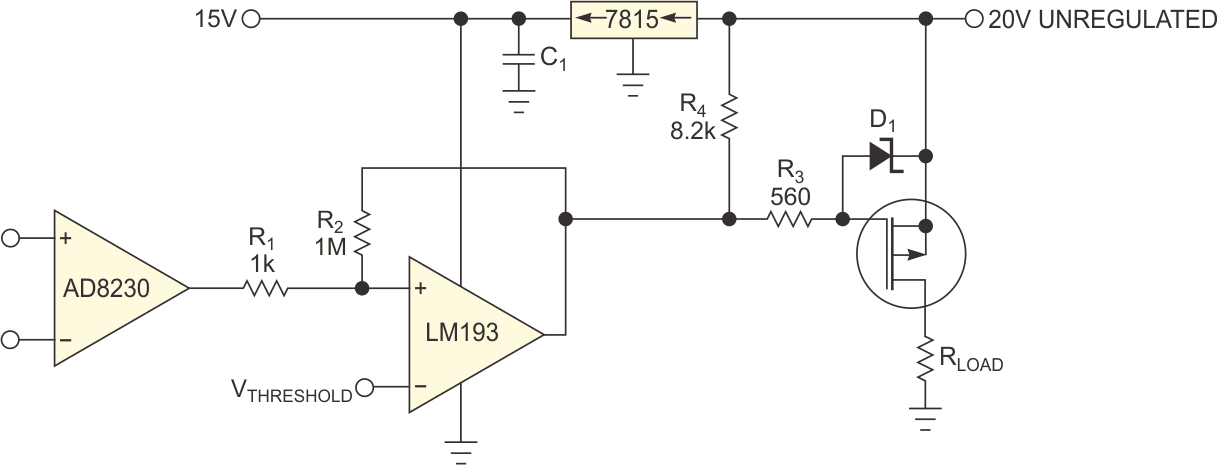
It is common practice to power a MOSFET with a comparator and with an unregulated voltage and to power the comparator driving it from a regulated one (Figure 1). Many loads are insensitive to driving voltage, so it would be a waste of money and power to use a regulated supply to drive the FET. It is also common practice to add resistors R1 and R2 to the comparator to put hysteresis in the operation, making the circuit less susceptible to noise, especially with slowly changing signals.
 |
|
| Figure 1. | Hysteresis components R1 and R2 tie to the unregulated supply, causing the comparator’s switching point to vary with the power supply. |
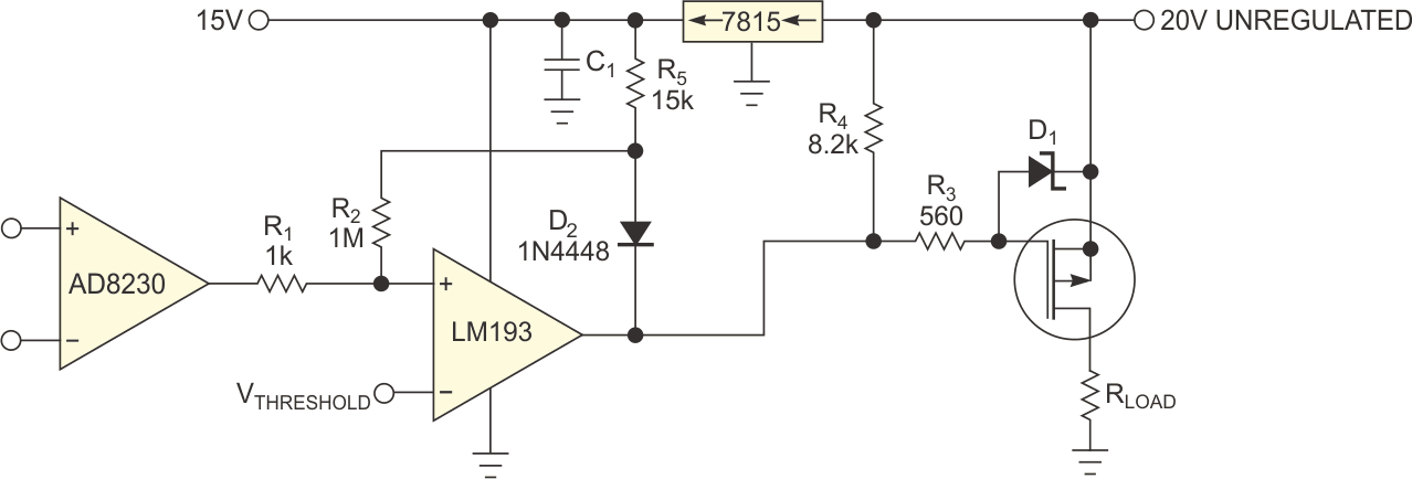
This circuit’s comparator changes with changes in the unregulated power supply. You can correct this problem by adding diode D2 and resistor R5 to the circuit (Figure 2). This approach isolates the hysteresis circuit from the unregulated output and instead drives it from the same regulated supply that drives the comparator. When the comparator is on, it drives the FET just as the original circuit does, pulling the P-channel FET gate toward ground. In both cases, you connect zener diode D1 to the FET gate to avoid exceeding the gate-to-source voltage. The improvements in the circuit in Figure 2 become apparent when the comparator turns off. In either case, R4 pulls the comparator’s open-collector output up to the positive power supply. In Figure 2, however, the diode isolates the hysteresis circuit from the power supply so that R4 pulls up R5 to the regulated 15 V, no matter how the power supply changes.
 |
|
| Figure 2. | Resistor R5 and an ORing diode isolate the hysteresis circuit from the power supply and keep the switching point constant no matter how the power supply changes. |
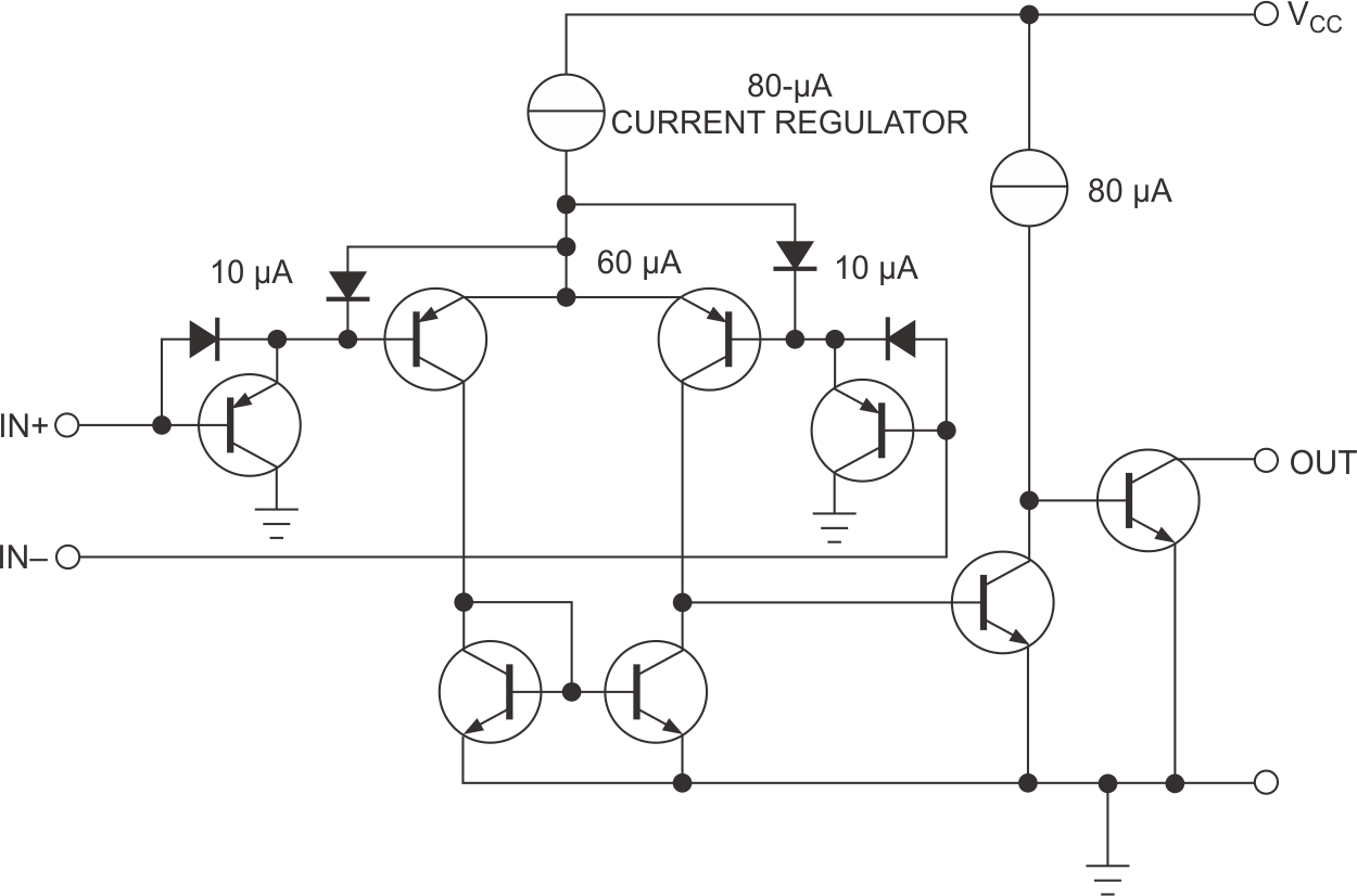
With a legacy comparator such as Texas Instruments’ LM193, the common mode of the inputs must stay well below the power-supply rail (Figure 3). The circuit requires 1.5 V head room at 25 °C and 2 V head room over temperature. Thus, for the circuits in figures 1 and 2, you cannot set the threshold voltage higher than 13 V. If your circuit requires a threshold voltage closer to the power rail, consider using newer parts with rail-to-rail inputs. You must use an open-collector or open-drain comparator for this hysteresis-isolation circuit to work. It would be incompatible with a totem-pole-output IC.
 |
|
| Figure 3. | The internal design of the LM193 comparator requires that you keep the input pins 2 V below the positive rail. |