The exposure tester in this Design Idea measures the on time of a light source, whether an LED, an incandescent lamp, a halogen lamp, or another source. It can be made with an ordinary stopwatch and a few simple components (figures 1 and 2). An electronic stopwatch needs two pulses to operate; one starts the internal counter, and another one stops it. A light source provides only one pulse, corresponding to the time the light is illuminated. This circuit generates a short trigger pulse whenever the luminous intensity changes.
 |
|
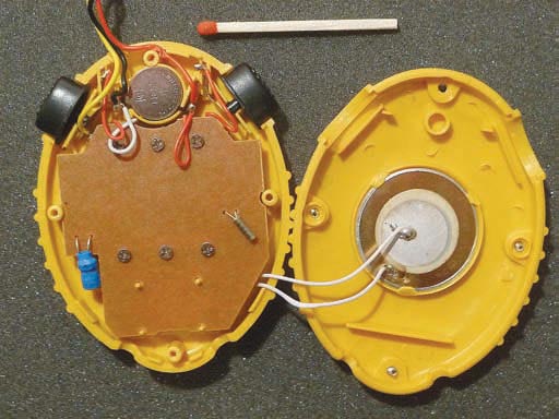
| Figure 1. | You build the circuit on a small prototype board that connects to the CG-501 stopwatch. |
 |
|
| Figure 2. | You can solder in pigtails to bring power, ground, and the trigger circuit to the prototype. |
When the photodiode is not illuminated, capacitor C1 charges to 1.5 V (Figure 3). The charge initially comes through the base-emitter junction of Q1 with a time constant that R1×C1 sets. Once C1 charges to 1.5 V minus the base-to-emitter voltage, R3 tops off the charge on C1 until it reaches 1.5 V. Because R3 and R1 are in series during this time, this topping off occurs with a slower time constant that (R1+R3)×C1 sets.
 |
|
| Figure 3. | This simple circuit times a light source. When you illuminate the photodiode, Q2 creates a pulse. When you remove the illumination, Q1 creates a pulse. |
When the photodiode is illuminated, photocurrent flows through R1, raising its voltage to more than 0 V, which drives the right side of C1 above the 1.5 V rail. The base of Q1 is reverse-biased and has no effect. However, Q2’s emitter is now forward-biased because R4 holds the base near 1.5 V. As Q2 turns on, the charge in C1 dissipates across R2, raising its voltage and creating a positive pulse. You convey this pulse to the stopwatch through R5, which is necessary in the case of extreme illumination of the photodiode. It limits the current into the stopwatch circuitry so that a large pulse cannot latch or overpower the internal stopwatch circuitry. The photocurrent creates a difference between 1.5 V and the voltage of R1; this difference causes C1, under illumination, to enter a final voltage.
When the photodiode is not illuminated, no photocurrent goes through R1, so C1 can charge back up as its left side goes to ground and its right side goes first to a base-emitter drop below 1.5 V and subsequently all the way to 1.5 V. Because the initial charge conducts through the base-emitter junction of Q1, that transistor again turns on, delivering a pulse across R2 and halting the stopwatch. Your selection of the value of C1 depends on the exposure time to be measured and on the photodiode used. The response rate of this circuit is approximately 500 msec. This example uses an Everlight PD333-3C/HO/L2 photodiode with a large spectral bandwidth, but any other photodiode or even a photoresistor will also work.