Some applications, such as ADC testing and calibration, require a DAC with extremely good resolution, monotonicity, accuracy, and resolution. In these categories of performance, the circuit in Figure 1 is hard to beat. Its typical specifications follow:
- Resolution = 32 bits = 3 × 10–10 = 1.2 nV = 192 dB.
- DNL (differential nonlinearity) = 27 bits = 400 nV = 162 dB.
- INL (integral nonlinearity) = 22 bits = 1.6 µV = 130 dB.
- Full-scale accuracy (untrimmed) = 11 bits = ±2.5 mV = 66 dB.
- Zero accuracy = 23 bits = ±500 nV±10 nV/°C = 140 dB.
- Ripple and noise = 21 bits = 2 µV p-p = 128 dB.
 |
|
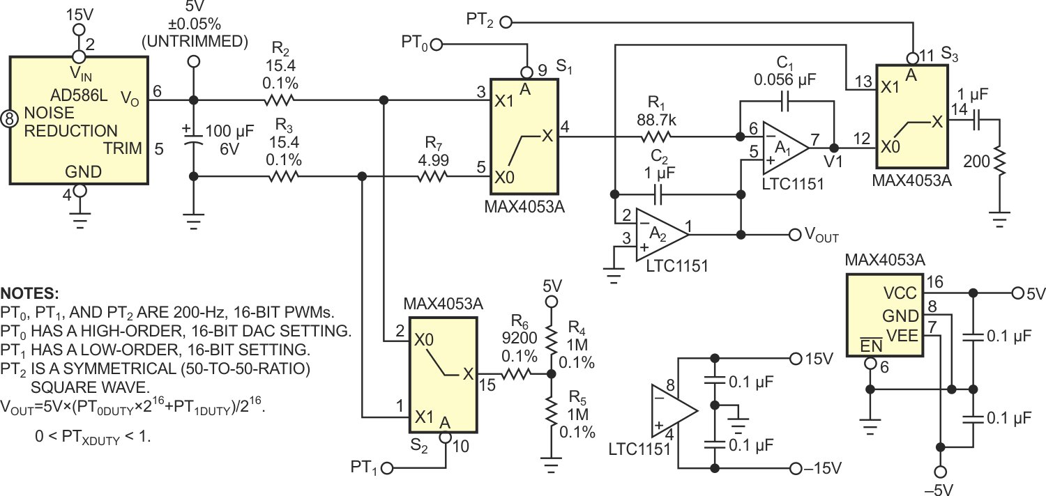
| Figure 1. | This DAC circuit sums two 16-bit PWM signals using precision analog switches to achieve 32-bit resolution. |
The basis of the DAC’s 32-bit resolution is the summing of two 16-bit PWM signals by analog switches S1 and S2 and precision resistor network R2 through R6. The DAC’s monotonicity and DNL are theoretically infinite, and, in practice, the only limit is the 1-to-216 ratio of R2: (R6 + R5 + RS2-ON) and R3: (R6 + R4 + RS2-ON). Typical accuracy of 0.1% resistors yields a DNL of approximately 0.1 ppm = 27 bits.
The less-than-0.1 Ω output impedance of the AD586 reference and the 130-dB CMR (common-mode rejection) of chopper-stabilized “zero-drift” amplifier A1 mostly limit INL. R7 suppresses a potential contribution from asymmetry in RS1-ON, yielding the typical INL of approximately 0.3 ppm = 22 bits.
Zero-accuracy and output-noise specs are at the low-microvolt level because of the excellent specifications of the LTC1151 A1 and A2 op amps and the charge-injection performance of the MAX4053A S2: approximately 0.4 ppm, or 23 bits.
The precision of the AD586L 5 V reference, which is ±500 ppm untrimmed, limits absolute accuracy. If your design requires greater accuracy, then you can use an Analog Devices simple trim circuit to further tweak it. There’s nothing critical about the suggested 200-Hz PWM cycle. You need to change only R1 and C1 to accommodate any convenient frequency. How closely the R1C1 time constant matches the PWM-cycle time determines the settling time of the A1-S2-A2 synchronous “zero-ripple” integrate-and-hold filter, and can be as fast as one cycle if the match is exact.