I needed a simple mist maker/humidifier for a project that I was working on. I found lots of ideas on the internet, but they all lacked in one area or another, so I decided to design one. The following lays out my easy-to-build ultrasonic mist maker. It works fine and is, by far, the easiest ultrasonic mist maker/humidifier that I’ve ever had to get going.

How does an ultrasonic mist maker work?
In an ultrasonic mist maker/humidifier (also called an ultrasonic atomizer), a piezo atomizer disc/transducer (ceramic humidifier) works by transposing high-frequency sound waves into mechanical energy that is transferred into a liquid, creating standing waves. As the liquid exits the atomizing surface of the disc, it’s broken into a fine mist of uniform micron-sized droplets, so the key component required for this little project is a particular (20-mm, 113-kHz) ultrasonic atomizer disc/transducer (see Figure 1).
 |
|
| Figure 1. | The ultrasonic atomizer disc/transducer |
When buying the transducer, make sure that is has a 113-kHz (±3 kHz) resonance frequency – another popular transducer has a 1.65-MHz (±0.05 MHz) resonance frequency, which is not compatible with this project!
Ultrasonic mist maker circuit
Transducer driver circuit
In Figure 2 is the circuit diagram of the final part of the project – the transducer driver. As shown in the circuit diagram, it’s a tricky oscillator design based on the ubiquitous tiny time chip NE555P (IC1) to generate proper drive pulse train for the atomizer transducer. In the circuit, the 5K multiturn trimpot (RP1) can be used to set the oscillator frequency to 113 kHz (±5 kHz) (TP1). Even though the ultrasonic mist maker device is configured to run on a single 5-Vdc to 12-Vdc input, this transducer driver needs a 20-Vdc to 26-Vdc (V_DRIVE) power supply channel in addition to a 5-V regulated DC supply rail. So a dedicated power supply circuitry will be introduced later to fulfill that crucial requirement.
 |
|
| Figure 2. | The circuit diagram of the final part of the project – the transducer driver. |
Because the circuit diagram is very simple and self-explanatory, I’m moving on to the rest of the project without giving a detailed circuit description. In Figure 3, you can see two oscillograms (TP2 & TP3) captured while I was running my ultrasonic mist maker prototype wired on a piece of common circuit board.
 |
|
| Figure 3. | Oscillograms taken at test points TP2 and TP3 of a working prototype of an ultrasonic mist maker. |
I bought the 113-kHz (20-mm) transducer from one of my trusty Chinese sellers at a cost of $2 per unit. Here’s an excerpt from its machine-translated Chinese datasheet provided by the seller:
- Diameter: 20 mm
- Frequency: 113 kHz (±3 kHz)
- Quiescent capacitor: 3,000 pF (±15% pF)
- Rated voltage: 70 V (max)
- Rated power: 2.5 W (normal use 1.5 W)
The prototype was successfully tested with a different 105-kHz (±5 kHz) transducer as well. Below are its key specifications:
- Diameter: 16 mm
- Operating frequency: 105 kHz (±5 kHz)
- Maximum power: 2 W
- Peak output voltage: 65 V (±5 V)
- Ripple (at maximum power): 100 mV
Power supply circuit
The power supply circuit (Figure 4) is a DC/DC boost converter regulator wired around the inexpensive and very popular eight-pin chip MC34063A (IC1). Here, its nominal output is trimmed to 20 Vdc by components R4 and R5. This circuit strictly follows the application example given in the datasheet, so you can tweak it if necessary.
 |
|
| Figure 4. | The power supply circuit. |
All electrolytic capacitors in the above two circuits are 40-Vdc–rated, while the 180-µH (180 µH to 220 µH) inductor (L1) is a 1-A “drum core”-type one. A small heatsink is necessary for the logic-level power MOSFET IRLZ44 (T1). Note that the power supply section is tailored deliberately to power up the entire ultrasonic mist maker comfortably from an external USB standard power supply. It accepts DC input in the 5-V to 12-V range from any another power source, such as a proper battery and/or wall adapter.
The optional momentary push switch (S1) in association with the 2K7 resistor (R6) lets you hike up the mist density for a short time only if desired. Note that when you push and hold S1, the final output voltage (V_DRIVE) will raise up to 26 Vdc until it gets released.
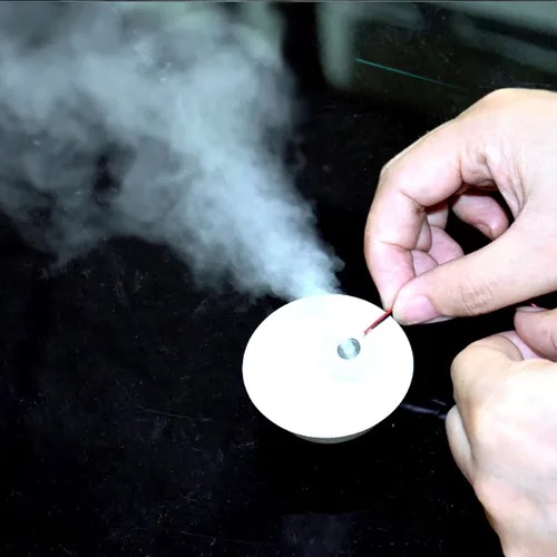
The near-final prototype has been tested inside my lab and worked well over the water’s surface with finer particles and a higher spray level, as expected. Sadly, I couldn’t find a DSLR camera to make a good movie of the test moments. However, you can see static images captured by my low-end smartphone camera in Figure 5.
 |
|
| Figure 5. | Testing a prototype of an ultrasonic mist maker. |
Final thoughts
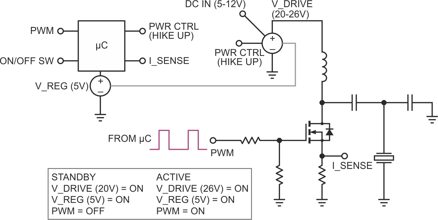
Actually, what I’d designed just after the idea spark is a microcontroller-compatible transducer driver circuit (see the blueprint in Figure 6.
 |
|
| Figure 6. | The microcontroller-compatible transducer driver circuit. |
Because my real intention is to develop and publish a salable design, I’m sure that a microcontroller at its core will give more flexibility and convenience. I don’t want to overkill an Arduino (or Attiny/STM flakes) for the task, but I’d like to try an inexpensive Chinese one-time programmable (OTP) microcontroller (like the PMS150 by Padauk). Although I don’t have a lot of experience with OTP microcontrollers yet (and hence opted for a 555 circuit), I’ll come up with an improved version of my ultrasonic mist maker for sure.
Engineers always want things not to be good but to be perfect every time!
…
Q: How do you find out the resonance frequency of an “unknown” ultrasonic transducer?
A: An ultrasonic transducer is a lump of metal and ceramic that has a particular resonant frequency. To operate the transducer at resonance, it must be driven with a high-frequency AC signal. The best way of determining the resonant frequency is to plot an impedance spectrum of the transducer. This is usually done with very expensive network analyzers, but it can also be done with a simple USB oscilloscope and sweep frequency generator if the oscilloscope software has suitable capabilities.