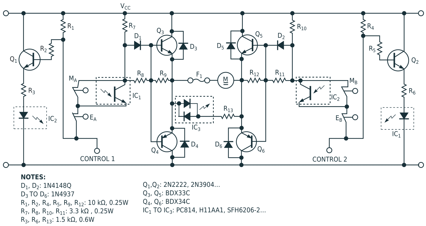
Figure 1 shows how to position a mechanical device into four discrete positions but with only two free outputs and one free input from the control system. The position depends on a set of cams and four corresponding limit switches. The 24V-dc motor comes with a worm gear. Darlington transistors Q3 to Q6 and resistors R7 to R12 form an H-bridge that drives the dc motor, M. Diodes D3 to D6 protect these transistors from inductive spikes. The outputs of the controller (not shown), connected to the Control 1 and Control 2 inputs, have open-collector structures that connect Control 1, Control 2, or both to ground upon activation. If you activate neither Control 1 nor Control 2, Q3 and Q5 conduct, receiving base current through R7 and D1 and R10 and D2, respectively. This action short-circuits (brakes) the motor. In this case, Q4 and Q6 are turned off. Optocouplers IC1 and IC2 are on, thereby short-circuiting the limit switches, MA and MB.
 |
|
| Figure 1. | This simple circuit provides four-position motor control with two inputs. |
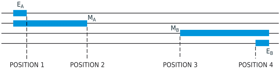
Activating only one control input (for example, Control 1), if the cam does not push open the corresponding limit switch, EA, causes Q3 to switch off and Q4 to switch on with R8 limiting the base current. Thus, the motor rotates until the cam pushes open limit switch EA (Position 1 in Figure 2). The limit switch, MA, has no influence because optocoupler IC1 short-circuits MA when Control 2 is in a high state. A similar, symmetrical operation occurs if you activate (ground) Control 2. In this case, the motor rotates to push open limit switch EB (Position 4). To bring the motor to one of the middle positions – say, Position 2 – you use the following procedure:
 |
|
| Figure 2. | Cams operate the limit switches in Figure 1, producing four discrete positions. |
With Control 2 high (not connected), activate (ground) Control 1. The motor rotates until it pushes open limit switch EA. The bases of Q3 through Q6 are all high.
Activate (ground) Control 2. The bases of Q5 and Q6 switch low. (MB and EB are closed.) The motor rotates in reverse until MA closes. At this time, all bases are low. Q4 and Q6 short-circuit the motor to ground, thereby braking it to a stop.
First activating Control 2 and then Control 1 brings the motor to Position 3, the edge of cam MB. Optocoupler IC3 remains on as long as the motor receives voltage. The output of IC3 connects to a feedback input of the controller. Thus, you can control whether the motor is rotating or stopped through this input. F1, a polymer-based resettable fuse, protects the motor and the circuit against overcurrent conditions, such as a stalled motor. You can mount the circuit in Figure 1 on small machine tools, such as a work-piece changer. The values of the components are not critical. The transistors are preferably Darlington types and, like the diodes, should have adequate ratings to accommodate the power-supply voltage and the motor current. (Don't forget the high inductance of the motor.) The components in Figure 1 accommodate a 24 V-dc, 2.5 A motor.