Of the many types of analog filters available to designers, few allow easy adjustments of the filter parameters. The biquadratic, or biquad, filter is an exception, however. You can change that filter's corner frequency (ω0), Q, and gain (H) by adjusting the values of three resistors. For that purpose, the lowpass biquad circuit of Figure 1 includes three digital potentiometers configured as variable resistors in the feedback loops. Altering the settings of these potentiometers changes the filter characteristics. The circuit produces corner frequencies of 5.5 to 55 kHz; Q values of 0.055 to 5.5, depending on the selected corner frequency; and gain of 1 to 100, also depending on the selected corner frequency.
 |
|
| Figure 1. | Digital potentiometers adjust the corner frequency, Q, and gain for this biquad analog filter. |
To tune the biquad filter, you set a corner frequency ω0 in radians per second by adjusting digital potentiometer IC2 via the SPI interface. In the same fashion, set Q by adjusting IC1 and gain by adjusting IC3.
Note that adjusting Q does not affect the corner-frequency setting, and a gain adjustment does not affect the settings of Q or the corner frequency. The three equations below demonstrate this orthogonal tuning for the biquad filter:


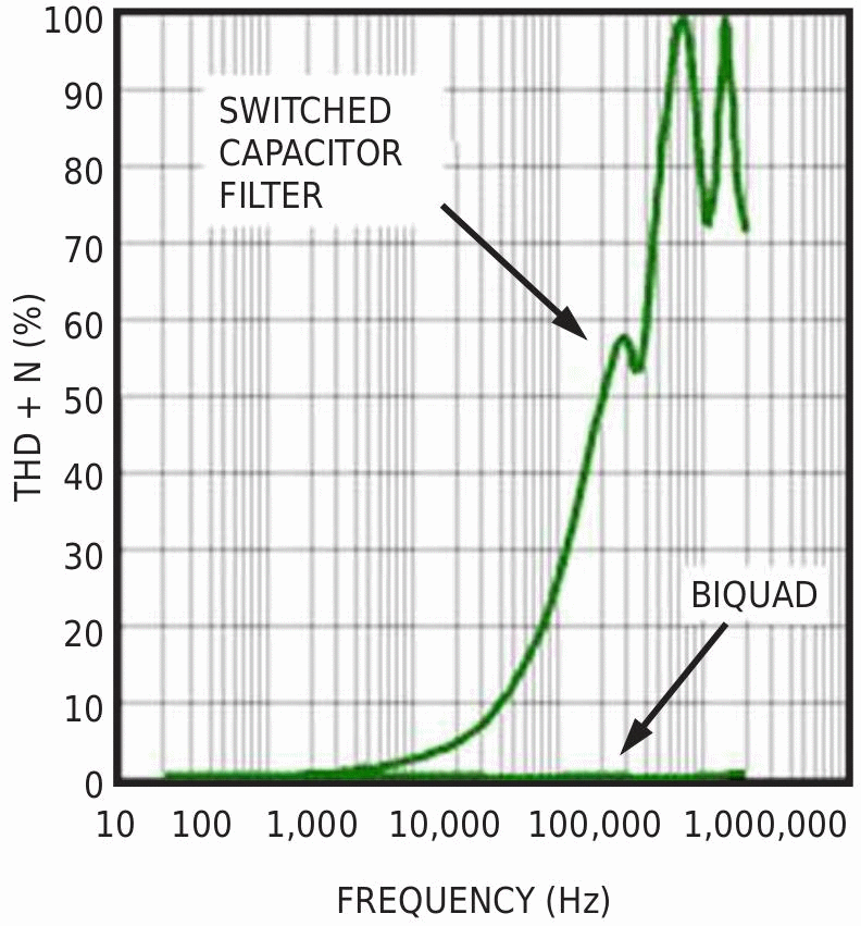
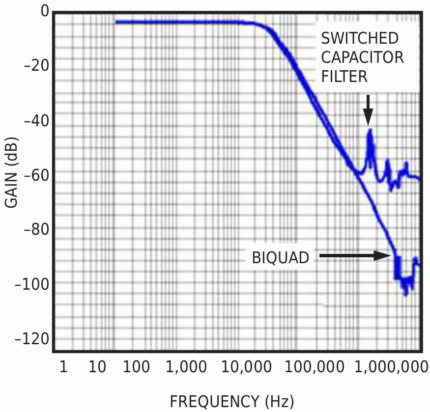
where RIC1, RIC2, and RIC3 are the input resistances of IC1, IC2, and IC3, respectively. The circuit in Figure 1 is substantially more complex than the switched-capacitor approach usually integrated into an IC, but the switching noise and low bandwidth of a switched-capacitor filter are unacceptable in many applications (Figure 2). A biquad filter offers better frequency and noise performance in exchange for more pc-board real estate. And, because monolithic switched-capacitor filters are usually expensive, the biquad circuit of Figure 1 may be a cost-competitive solution. Many filter applications require higher supply voltages, bipolar operation, or both, so the single 5 V supply associated with most switched-capacitor filters may be inadequate for a given application. You can implement ±15 V voltage rails using digital potentiometers and high-voltage op amps, such as the MAX5438 and MAX437.
|
|||||
| Figure 2. | Noise (a) and low bandwidth (b) plague switched-capacitor filters. The biquad filter of Figure 1 maintains less than 1% THD+N over the range 20 Hz to 200 kHz. |
||||
The biquad filter is not limited to the lowpass response. You can implement highpass, bandpass, bandstop, and allpass filters by adding a fourth op amp to selected terminals of the original lowpass design (Figure 3).


