This is a new implementation of the AVR DDS signal generator v2.0, already published in scienceprog.com. It is obvious that full credit for the original schematic and the firmware goes to its original creator. Presented here is a different PCB that is compact, single sided with only through-hole components for easy construction.
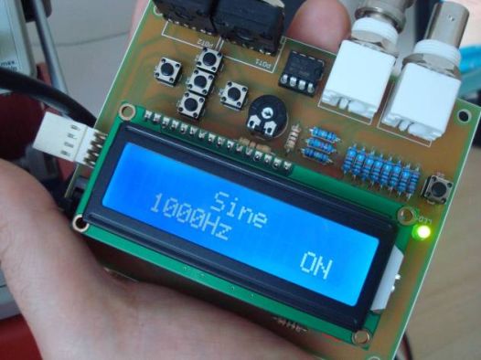
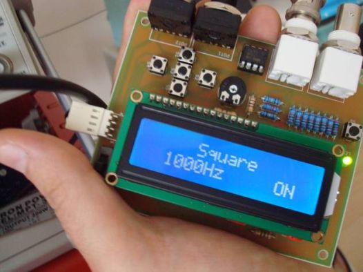
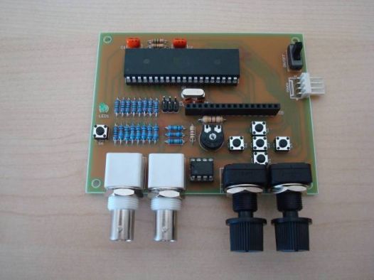
The function generator features two BNC outputs : one for the high speed [1 to 8 MHz] square signal (BNC1) and another for the DDS signal (BNC2). Offset and amplitude can be regulated by two potentiometers : offset in range of +5V to -5V (POT1) and amplitude in range of 0 to 10V (POT2). Up and down arrow buttons are used for changing the function type (sine, triangle etc.) while left and right arrow buttons are used for changing the frequency value. There is also a separate menu for changing frequency step. When the middle button is pressed, the signal generation starts. Middle button is pressed again for stopping the signal. More details can be found in the original site.
Schematic
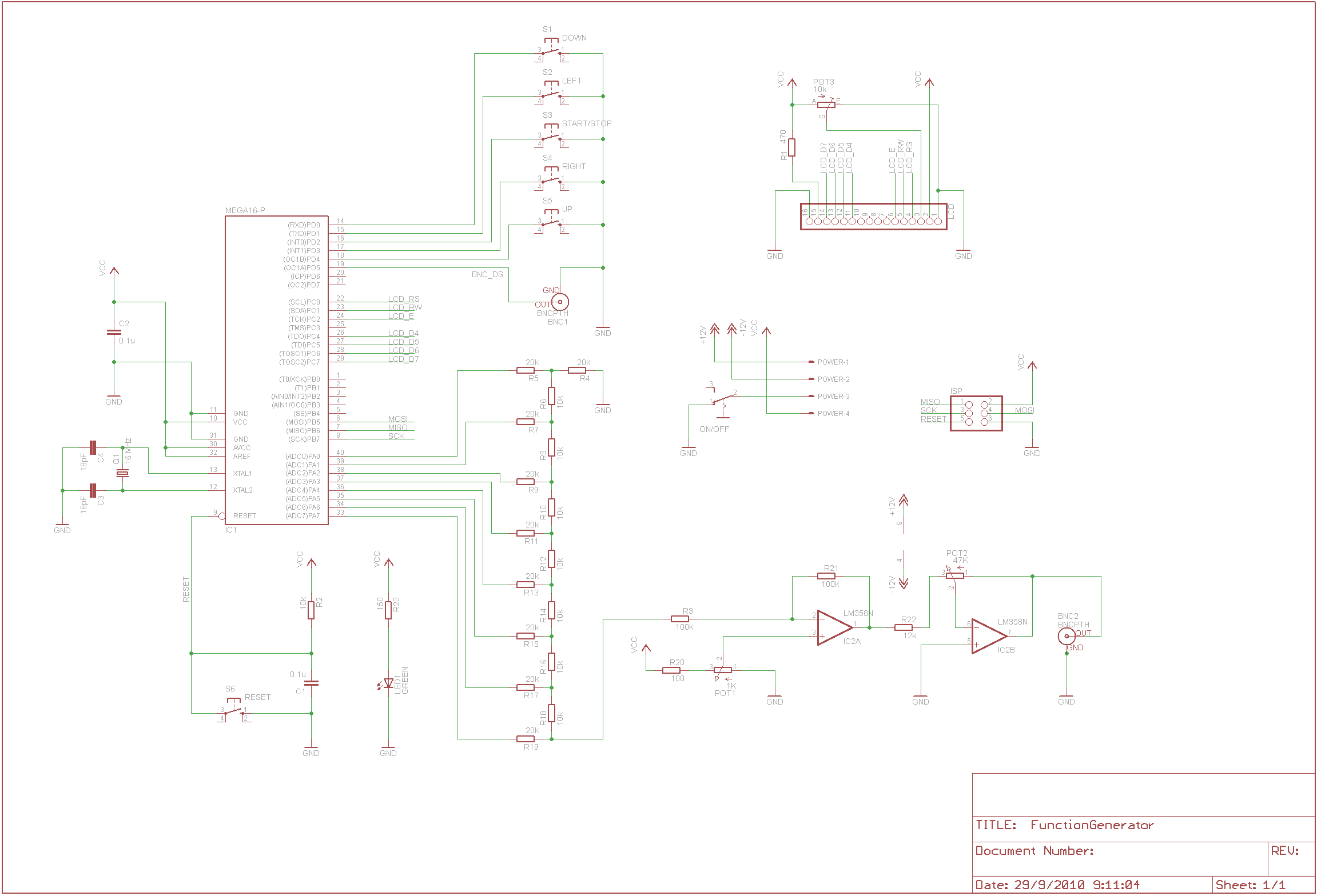
EAGLE Schematic (only a status led and an on/off switch was added)
click on image for higher resolution
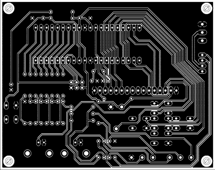
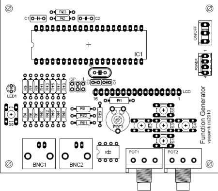
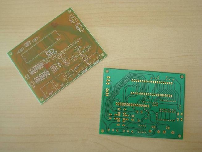
PCB
Parts List
|
Part |
Value |
|
R1 |
470 Ω ½W 5% |
|
R2 |
10 ΚΩ ¼W 5% |
|
R3 |
100 ΚΩ ¼W 1% |
|
R4 |
20 ΚΩ ¼W 1% |
|
R5 |
20 ΚΩ ¼W 1% |
|
R6 |
10 ΚΩ ¼W 1% |
|
R7 |
20 ΚΩ ¼W 1% |
|
R8 |
10 ΚΩ ¼W 1% |
|
R9 |
20 ΚΩ ¼W 1% |
|
R10 |
10 ΚΩ ¼W 1% |
|
R11 |
20 ΚΩ ¼W 1% |
|
R12 |
10 ΚΩ ¼W 1% |
|
R13 |
20 ΚΩ ¼W 1% |
|
R14 |
10 ΚΩ ¼W 1% |
|
R15 |
20 ΚΩ ¼W 1% |
|
R16 |
10 ΚΩ ¼W 1% |
|
R17 |
20 ΚΩ ¼W 1% |
|
R18 |
10 ΚΩ ¼W 1% |
|
R19 |
20 ΚΩ ¼W 1% |
|
R20 |
100 Ω ¼W 5% |
|
R21 |
100 ΚΩ ¼W 1% |
|
R22 |
12 ΚΩ ¼W 1% |
|
R23 |
150 Ω ¼W 5% |
|
POT1 |
1 ΚΩ linear potentiometer |
|
POT2 |
47 KΩ linear potentiometer |
|
POT3 |
10 ΚΩ trimmer |
|
C1 |
100 nF MKT/polyester |
|
C2 |
100 nF MKT/polyester |
|
C3 |
18 pF ceramic |
|
C4 |
18 pF ceramic |
|
Q1 |
16 MHz crystal |
|
IC1 |
ATMEL ATMEGA16P |
|
IC2 |
LM358N |
|
BNC1 - BNC2 |
BNC female connector |
|
S1 - S6 |
Push button |
|
LCD Header |
Female header 16 pin for LCD |
|
LCD Module |
HD44780-based 2×16 character LCD |
|
ISP |
Male header 2x3 for ISP |
|
POWER |
Female header 4-pin for power as follows : |
|
LED1 |
3 mm green led |
|
ON/OFF |
Miniature on/off switch |
Changes in firmware
Because of the present LCD character orientation, which is different from the original implementation (180 degrees), the following changes in main.c were made :
Buttons LEFT and RIGHT were reversed :
#define LEFT 3//PORTD
#define RIGHT 1//PORTD
Buttons TOP and BOTTOM were reversed :
#define DOWN 4//PORTD
#define UP 0//PORTD
For the latest version of AVR-GCC compiler, the following changes should be made (according to Geoff comment on scienceprog.com) :
struct signal{
volatile uint8_t mode; //signal
volatile uint8_t fr1; //Frequency [0..7]
volatile uint8_t fr2; //Frequency [8..15]
volatile uint8_t fr3; //Frequency [16..31]
volatile uint32_t freq; //frequency value
volatile uint8_t flag; //if 0 generator is OFF, 1 is ON
volatile uint32_t acc; //accumulator
volatile uint8_t ON;
volatile uint8_t HSfreq; //high speed frequency [1...4Mhz]
volatile uint32_t deltafreq; //frequency step value
}SG;
The ATMEGA16 fuses should be :
HIGH = 0×59
LOW = 0xCF
This is interpreted to the following options checked (all others unchecked): OCDEN, SPIEN, BOOTSZ1, BOOTSZ2. SUT, SUT0